Download
1 / 68
680 likes | 696 Views
This document provides information on VXD installation options, remote vacuum connection, baseline installation procedure, and the preparation required before making a decision.

E N D
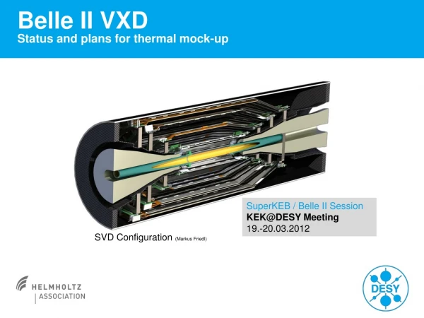
Very preliminary draft VXD installation S. Tanaka (KEK)
VXD Installation options Remote Vacuum Connection: *VXD and QCS are independently installed like SVD2 *Requiring space for RVC mechanism *Service work start after VXD installation *The RVC mechanics have confirmed by some tests *Installation tool design (for conceptual test) is ongoing (Installation procedure other than RVC will validate before decision) C.Niebuhr,K.Gadow Baseline installation procedure: *VXD and QCS are connected before installation *Requiring space for VXD support ring to align position *Service work of FW should finished before installation *Mechanical analysis ->done *Installation test with mock-up->done other than cable stress estimation to VXD structure T.Kohriki, K,Kanazawa • 2013 Oct: Starting design work of VXD installation sub-parts • 2013 Nov.: Decision of installation procedure by internal review The decision will be done in Nov.
VXD mechanics Do you have good picture including SVD service > Tschalie?
Discussion slide Request from reviewer • We hope that the installation procedures and sequence can be discussedin some detail witha full accounting of clearancesand the remote vacuum connections. (by Tschalie ?) • Would it be possible to also post the specifications for installation? • For example, what is the target relative alignment between the PXD and SVD, between the end rings and support rings that control the twist of the SVD, module installation precision and things of that nature.(L-shape sensor for inside or additional sensors to monitor position on installation) These are to be answered in Shuji Tanaka's talk.Obviously he needs input from benny. Answer slides will be prepared after meeting in Sunday and Monday This is not only for AIM but also for baseline option
What should be prepared before decision • Installation procedure animation image with realistic. • Mechanical analysis on each typical step • Stress to CFRP (because of gluing connection with End-flange) • Deformation of VXD by stress on installation • Installation test with mockup • Showing feasibility of service work with space margin • Ensuring repeatability of VXD Installation and dismantle • Decision should be done by Belle II EB with machine group leader in Nov. B2GM
Comparison table Should discuss on meetings in Sunday and Monday
VXD load test into CDC As a result, The VXD structure sink ( CDC structure deform) about 180-190um (200umwas expected)with 80 kg of VXD mockup structure and additional weight(This load was applied on both End flange. )
QCS tip position shift on install · How much the tip of the QCS used in KEKB shift at collision point, based on the movement test of the QCS moving frame. -From spec of the frame, horizontal and vertical variation should be within 0.5 mm. the results of the test are satisfied with it move. However, if we look at the tip of the QCS, the tip of the QCSR was shifting about 1 mm in vertical. On the other hand, on QCSL case, 0.2mm variation in vertical and 0.4mm in horizontal The difference is mainly caused by the adjustment of the position of the rail. In the current scenario, the movement of the QCS tip should be kept below 0.5 mm.
Floor for QCS stage Floor will be very flat by adopting self-leveling method
Installation Scenario - Baseline T. Kohriki Design of support structure is not started yet. (expected from September)
Vertex detector installation The cabling and piping work should be finished before installation. The cables on backward are put on sled The sled guide is fixed on backward side
Vertex detector installation The guide roller keep the weight until touching the roller on CDC Inner cylinder
Vertex detector installation After touching the roller in CDC inner cylinder , Guide roller will be removed.
Vertex detector installation On this case, the roller on backward side keep the Weight (CFRP should not attach in any position)
Vertex detector installation VXD is connected with CDC at backward (xyz) Forward position is fixed for x-y position with guide roller
SVD support ring at forward region Positioning guide pin (CDC side) Release control rod after install (QC cryostat side) Guide roller to keep weight of SVD
QCS-VXD Joint The junction between VXD and the cryostat must be loosened so that a possible motion of the cryostat after exciting magnets may not exert a force on VXD. VXD arm Pin(f 10) QCS arm Screw bolt(M8) Nut-cramp (M8) Ring-cramp(f 8.2) The pin support the support ring of VXD. By loosening the nut-cramp, VXD arm and QCS arm are mechanically disconnected. The tolerance is 1 mm. (Kohriki)
Fixing Backward Remove support extension Remove the upper half of the support ring and adopt brackets connecting CDC ringand VXD Remove other half of the support ring and adopt brackets connecting CDC ringand VXD VXD detector is fixed at backward end for x, y, z axis
BP20kg_Sled:SUS1mmt Equivalent stress:Max 32MPa IR weight ~60kg Rib is added Deformation:Max1.3mm CFRP stress :Max 11MPa The equivalent stress depends on the weight of structure
Installation test with mockup On Dec 2012. we have tested this installation procedure with mockup.
Schematic view of RVC installation procedure Apply similar procedure with Belle SVD2 case Almost similar with Belle SVD Procedure without support tube Discussion of detail procedure is ongoing
VXD Installation Step 1 Installmounting tube (stainless steel) and connect to inner endring of CDC (both sides) bwd fwd
VXD Installation Step 2 install support structures on both sides bwd fwd
VXD Installation Step 3 install mounting tube extensions on both sides bwd fwd
VXD Installation Step 4 connect cable trays on both sides of VXD bwd fwd 40 kg 80 kg 40 kg sliding parts
VXD Installation Step 5 lower VXD system to mounting tube extension bwd fwd
VXD Installation Step 6 bend CO2 pipes and fiddle through CDC as far as possible bwd fwd
VXD Installation Step 7 push VXD system by hand through mounting tube, helping from bwd with rope or better divided rod … bwd fwd
VXD Installation Step 8 … until it reaches the final position bwd fwd
VXD Installation Step 9 fix the bwd end of VXD to CDC endring (at 3 flange-positions, 0 degree of freedom at bwd) bwd fwd
VXD Installation Step 10 fix the fwd end of VXD to CDC endring (with long fixing screw, 1 degree of freedom in moving direction at fwd) bwd fwd
VXD Installation Step 11 temporarily suspend cable/pipes on fwd end bwd fwd
VXD Installation Step 12 remove extension on fwd end bwd fwd
VXD Installation Step 13 Install the first fwd cable on CDC inner wall and hang all other cable on hooks which are mountet on the fwd outside wall of the CDC bwd fwd
VXD Installation Step 14 remove cable tray on fwd end bwd fwd
VXD Installation Step 15 remove the mounting tube flange fwd bwd fwd
VXD Installation Step 16 Install all other fwd cable bwd fwd
VXD Installation Step 17 temporarily suspend cable/pipes on bwd end bwd fwd
VXD Installation Step 18 Pull extension bwd which is connected with the mounting tube bwd fwd
VXD Installation Step 19 Remove extension bwd bwd fwd
VXD Installation Step 20 remove mounting tube bwd fwd
VXD Installation Step 21 Install the first bwd cable on CDC inner wall and hang all other cable on the hook which is mountet on the bwd outside wall of the CDC bwd fwd
VXD Installation Step 22 remove cable tray on bwd end bwd fwd
VXD Installation Step 23 Install all other cable bwd bwd fwd
BRM (BaselineRetraction Method) (for emergency extraction together with QCS on fwd) (V2.2)