Download
1 / 34
370 likes | 496 Views
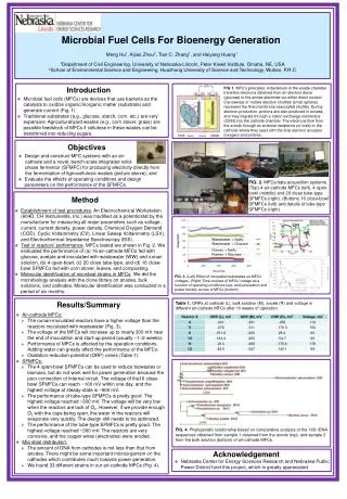
Microbial Fuel Cells. Keith Scott. CONTENT Fuel Cells and Biological Fuel Cells Mechanisms Research Challenges MFC performance MFC prospects. FUEL CELL Grove Genesis 1839 - 1842. The simplest realisation – the H 2 /O 2 fuel cell. O 2. e -. Pt. Pt. 2H 2 4H + + 4e -.

E N D
Microbial Fuel Cells Keith Scott CONTENT • Fuel Cells and Biological Fuel Cells • Mechanisms • Research Challenges • MFC performance • MFC prospects
FUEL CELL Grove Genesis 1839 - 1842 The simplest realisation – the H2/O2 fuel cell O2 e- Pt Pt 2H2 4H+ + 4e- 4H+ + 4e- + O2 2H2O Cathode (Pt catalyst) Anode (Pt catalyst) Electro lyte H+ Positively charged ions to pass through the electrolyte. The negatively charged electronmust travel along an external circuit to the cathode, creating an electrical current. H2 H2O • The electrolyte can be liquid, solid or polymeric and essentially: • Separates fuel and oxidant • Facilitates ion transport between anolyte and catholyte • Prevents electrical short circuit between anode and cathode
Bioelectrochemical energy generation R R e- e- - more robust - better defined system - oxidizing substrate completely - poisoning - mixed substrates - reaction pathways more difficult Glucose O2 Acetate O2 e- e- e- e- e- e- Cytc PQQ Micro- organism COx FAD H2O Gluconic acid H2O CO2 CATHODE CATHODE ANODE ANODE Biological fuel cells Enzyme and whole cell catalysis Enzymatic fuel cells Use isolated and purified enzymes to act as specific catalysts Microbial fuel cells Use whole living cells to continously supply the biocatalysts
MFC Applications • Enhanced Water and Waste treatment • Energy Production • Hydrogen Generation • Alternative Reductions- e.g. production of peroxide • Alternative oxidations- using electron accepting (cathodic) bacteria
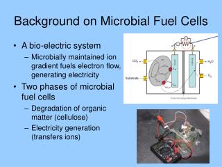
e - S M OX r r E B P M RED MFC- A Complex System • Anode-attached and suspended biomass • Several metabolic types • Multiple biological, chemical and electrochemical reactions • Reactions occur in the bulk liquid, the biofilm and the electrode surface Electrical load Electrical mod Electrical A A Bulk liquid Biofilm Anode Anode Cathode Cathode Membrane Membrane Substrate Electrochemical model Substrate e e - - Bacteria Bacteria Oxygen Oxygen S S M M OX OX r r r r E E B B P P M M RED RED Aerobic anaerobic Biofilm Biofilm Boundary Boundary cells cells layer layer
Microbial fuel cells: Biology/Chemistry/Physics e- e- H+ H+ 5 6 7 10 2 3 9 1 8 oxygen transport (bulk, b.l.) substrate and mediator transport (bulk, boundary layer, biofilm) electrical resistance 8 9 1 2 4 anodic reaction H+ transport (bulk, b.l., membrane) cathodic reaction 3 10 6 5 7 Performance limitations R e- • catalysts for the ORR: • - Pt/C, high cost detrimental • few non-platinised catalysts • MnOx/C 4 products P O2+ 4H+ + 4e- → 2H2O S ANODE CATHODE O2 substrate
Research Themes • Anode materials – carbons (WC,…) • Biofilm mechanisms and anodophiles- Geobacteraceae, Desulfuromonaceae, Alteromonadaceae, Enterobacteriaceae, Pasteurellaceae, Clostridiaceae, Aeromonadaceae, and Comamonadaceae are able to transfer electrons to electrodes. • Cathodes (activated carbons, porphyrins, MnOx, biological……) • Separators (Tyvek, Scimat, Entek, ptfe.. ) • Electrode structure (gas diffusion, ptfe bonded…) • Parameters (Temp, pH, COD, HRT, conductivity) • Cell design (anode structure, scale-up, flow through) • Modelling
Microbial Fuel Cells: Mechanisms of electron transfer cytochromes Sox Iox 2. Direct electron transfer Ired e- Sred 1. Product electron transfer Pox Sox e- Iox Ired Pred Sred
Microbial Fuel Cells: Mechanisms of electron transfer e- Sox Iox metal oxides Ired Sred 3. Newer hypotheses for direct transfer e- Sox Iox "nano-wires" Ired Sred
Microbial Fuel Cells: Mechanisms of electron transfer mediator Mox Sox e- Iox diffusive Mred Ired Sred mediator 4. Mediated electron transfer Sox Iox M non-diffusive Ired e- Sred
Microbial Fuel Cells Faster at temperatures above 30ºC METHANOGENESIS CO2 + H2 Metano + ACETOGENESIS METHANOGENESIS VFAs Acetic ANODOPHILIC OXIDATION ACIDOGENESIS Aminoacids Fatty acids Glucose Carbohydrates Lípids Proteins HYDROLYSIS e- + CO2 + H+ Extracellular enzymes ANODOPHILIC OXIDATION Faster at temperatures below 10ºC COD REMOVAL
Biofilms on anodes What is the biofilm area? Biofilm on graphite cloth Biofilm on graphite paper
Biofilms on anodes What is the anode area? Biofilm on reticulated vitrous carbon Biofilm surface on graphite
Microbial Fuel Cells Cathode Material • Linear sweep voltammetry of O2 reduction:Iron phthalocyanine supported on KJB (FePc-KJB) carbon demonstrated higher activity towards oxygen reduction than Pt in neutral media. Pt and metal phthalocyanine on KJB;. (Passive electrode without air sparging, catalyst loading 1 mg/cm2, 50 mM phosphate buffer with nutrients, pH=7.0, T= 30 oC, scan rate 1mV/s
Microbial Fuel cell Power Cathode Material • MFC polarisation and power density-With FePc-KJB as the MFC cathode catalyst, a power density of 634 mW m-2 which was higher than that obtained using the precious-metal Pt cathode. Using a high surface area carbon brush anode the power density was increased to 2011 mW m-2. CARBON FELT CARBON BRUSH FePc catalyst cathode and a graphite brush (30 oC, 200 mM PBM, pH 7.0, 1 g L-1 acetate). Various cathode catalysts (50 mM phosphate buffer, T= 30 oC).
Microbial Fuel cell Power from Wastewater Cathode Material COST ( 0.1 mg/cm2 Pt. 1.0 mg/cm2 Mn) Mn: 0.02 $ g-1 Pt: 23 $ g-1 0.2 $ m-2 MnOx/C 23 $ m-2Pt/C
Packed Bed of Graphite Granules anode. Variation of current with time for electrochemically-active bacterial enrichment of SCMFC The first 8 batches were performed with anaerobic sludge as inoculum (0.5% by volume) and AW (1000 ppm COD). The 9th batch was performed with AW containing 1000 ppm as COD and no inoculum. Anode cross sectional area: 12.5 cm2. External resistance: 500 Ω.
MFC generate electricity from full-strength brewery wastewater (2,239 mg-COD/L, 50mM PBS added) with the maximum power density of 483mW/m2 (12W/m3) at 30C and 435mW/m2 (11W/m3) at 20C, respectively- Y Feng et al WST 2008
Effect of the loading rate on the SCMFC performance. Rext 100 Ω. Complex System- Use models to better understand behaviour
Model -biofilm+suspended cells and mediator adv. adv. diff. diff. diff. react. react. react. Solute concentration Liquid Biofilm Here we measure! Substrate Product Electrochemical product Electrochemical reactant Electrode distance Biofilm thickness Biofilm model (solutes)
Microbes meet with resistance • The biochemical model is based on the IWA anaerobic digestion model with electrogenic acetate oxidation and an electron-transfer mediator Batstone D.J., Keller J., Angelidaki I., Kalyuzhnyi S.V., Pavlostathis S.G., Rozzi A., Sanders W.T.M., Siegrist H., Vavilin V.A. (2002) Anaerobic Digestion Model No. 1 (ADM1), IWA Task Group for Mathematical Modelling of Anaerobic Digestion Processes. London: IWA Publishing.
40 30 35 25 Current 30 density 20 25 Current density, j (mA/m2) Total charge (C) 20 15 15 Charge 10 10 5 5 0 0 0 5 10 15 Time (days) Integrating modeling and experimentationExamining effect of external load on MFC properties • Model outputs • Time-dependent production of Current , Voltage • Time-dependent bulk substrate, intermediate and product concentrations • Power, Coulombic yields • Current-voltage, current-power curves • Spatial distributions of chemical species • Spatial distributions of biomass species
Integrating modeling and experimentation • Qualitative predictions • Increasing external resistance should reduce the rate of electron transfer from the substrate to the anode • Electrogens become less competitive • Methanogens become more competitive • Reduced current/charge and Coulombic yield • Community composition should alter with external resistance • Biomass of electrogens should be reduced
Effect of external resistance on COD removal 600 • Experimental 100 Ohms 500 COD (exp), 0.1 K (1) COD (exp), 0.1 K (2) 400 COD (sim), 0.1 K COD (g/m3) 300 COD 200 100 0 0 2 4 6 Time (days)
100 90 80 70 60 50 40 30 20 10 0 Effect of external resistance on COD removal • Higher external load shows reduction in COD removal efficiency detected experimentally • Systems run as MFC have improved COD removal compared to controls COD removal (%) OCV control 1 kohms 25 kohms 50 kohms 10 kohms 0.1 kohms
Effect of external resistance on the anode community • Denaturing gradient gel electrophoresis of anode communities M I1001000 M 1000025000 M 50000OCV M Cont. • Anode bacterial communities developed at 100 to 50,000 ohms characterized • Anode biomass harvested at end of experimental run • DNA extracted and 16S rRNA gene fragments amplified by PCR • 16S rRNA gene fragments analyzed by DGGE to provide a community fingerprint
Prospects for wastewater MFC and biological treatment • External load has profound effects on the anode community and MFC performance • Even if MFC never produce useful amounts of electricity, still potential benefits for wastewater treatment • Can external load be used to “tune” • Treatment performance? • Sludge yield? • If lower external load selects for electrogens, should MFC anode communities be conditioned under low external load to maximize electrogen colonization?
PROSPECTS The key issues for a microbial (bio-electrochemical) fuel cell reactor for the recovery of energy or production of valuable chemicals relate to: • Reactor Cost (in relation to product value including wastewater treatment) • MFC Reactor Design • Reactor scale-up to suitable plant production size • Reactor Durability • ANODE DESIGN and CONFIGURATION CRUCIAL • WasteWater polishing
Reactor Cost • If we take a potential power capability of1.0 kW per m3 of reactor containing 100 cell equivalents giving power of 10 W/m2 of cross-sectional area. • The energy produced would be 8000 kWh/year with a value of approximately £800/year. • Working on a simple payback over 5 years this would be equivalent to a cost from generating electricity of £4000. • Thus the cost of an individual cell would be of the order of £40 (/m2). • These are quite challenging costs and rule out the use of precious metal (including silver)for catalysts and ion-exchange membrane materials that are frequently used in microbial fuel cells.
Acknowledgments • EU Marie Curie ToK • EPSRC • Northumbrian Water • Research Group- Profs I M Head, T Curtis Dr E Yu • Drs K Katuri, M Di Lorenzo , I Roche, M Ghangreghar, B Erable, N Duteanu, Y Feng • PhDs- Amor Larrosa Guerrora, Jamie Hinks, Sharon Velasquez Orta, Beate Christgen