Download
1 / 32
320 likes | 326 Views
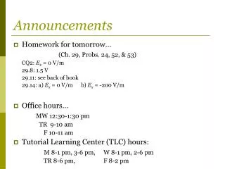
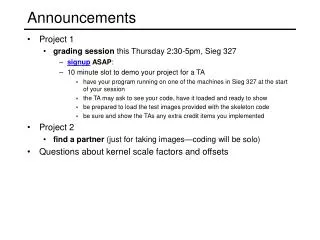
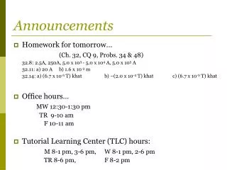
Announcements. Assignment 7 due now or tommorrow Assignment 8 posted Due Friday 25 th . All project components arrived? Dates Thursday 12/1 review lecture Tuesday 12/6 project demonstrations in the lab (no presentations) Sunday 12/11 project reports due to me by email

E N D
Announcements • Assignment 7 due now or tommorrow • Assignment 8 posted • Due Friday 25th. • All project components arrived? • Dates • Thursday 12/1 review lecture • Tuesday 12/6 project demonstrations in the lab (no presentations) • Sunday 12/11 project reports due to me by email • Tuesday 12/13 final exam, 1pm-3pm here.
Lecture 21 Overview • More Sequential Logic Design • Another counter example • “don’t care” conditions • Ant Brain Example
FSM Design Procedure • Start with counters • Simple because the output is just the state • Simple because there is no choice of next state based on inputs • Draw the finite state diagram • State diagram to state transition table • Tabular form of state diagram • Similar to a truth-table • State encoding: how do you represent the state in binary? • Decide on representation of states (e.g. traffic light green = what in binary?) • For counters it is simple: just its value • Implementation • Flip-flop for each state bit • Use Karnaugh maps to find combinational logic, based on state encoding
current state next state0 000 001 11 001 010 22 010 011 33 011 100 44 100 101 55 101 110 66 110 111 77 111 000 0 010 011 001 1 2 3 000 100 3-bit up-counter 4 0 110 101 111 7 6 5 FSM Design Procedure: State Diagram to Encoded State Transition Table • Transition table is just a tabular form of the state diagram • Shows all of the possible transitions • Like a truth-table (specify output for all input combinations) • Encoding of states: easy for counters – just use output value
current state next state0 000 001 11 001 010 22 010 011 33 011 100 44 100 101 55 101 110 66 110 111 77 111 000 0 010 011 001 000 100 3-bit up-counter 110 101 111 FSM Design Procedure: State Diagram to Encoded State Transition Table • Tabular form of state diagram • Shows all of the possible transistions • Like a truth-table (specify output for all input combinations) • Encoding of states: easy for counters – just use output value
C3 C3 1 1 0 0 0 1 1 0 1 1 0 0 1 0 0 1 C1 C1 C2 C2 C3 C2 C1 N3 N2 N10 0 0 0 0 10 0 1 0 1 00 1 0 0 1 10 1 1 1 0 01 0 0 1 0 11 0 1 1 1 01 1 0 1 1 11 1 1 0 0 0 N1 N2 N3 C3 C3C2 00 01 11 10 C1 0 0 0 0 1 1 1 0 1 1 C1 C2 Implementation current • Each state bit requires one D flip-flop • Combinational logic is needed to implement transition table next notation to show function representing input to D-FF N1 := C1' N2 := C1C2' + C1'C2 := C1 xor C2 N3 := C1C2C3' + C1'C3 + C2'C3 := C1C2C3' + (C1' + C2')C3 := C1C2C3' + (C1C2)'C3 := (C1C2) xor C3 Karnaugh maps for each output:
C3 C2 C1 N3 N2 N10 0 0 0 0 10 0 1 0 1 00 1 0 0 1 10 1 1 1 0 01 0 0 1 0 11 0 1 1 1 01 1 0 1 1 11 1 1 0 0 0C3 C2 C1 N3 N2 N10 0 0 0 0 10 0 1 0 1 00 1 0 0 1 10 1 1 1 0 01 0 0 1 0 11 0 1 1 1 01 1 0 1 1 11 1 1 0 0 0 Implementation • Each state bit requires one D flip-flop • Combinational logic is needed to implement transition table current next N1 := C1' N2 := C1C2' + C1'C2 := C1 xor C2 N3 := C1C2C3' + C1'C3 + C2'C3 := C1C2C3' + (C1' + C2')C3 := (C1C2) xor C3
In C1 C2 C3 N1 N2 N30 0 0 0 0 0 00 0 0 1 0 0 00 0 1 0 0 0 10 0 1 1 0 0 10 1 0 0 0 1 00 1 0 1 0 1 00 1 1 0 0 1 10 1 1 1 0 1 11 0 0 0 1 0 01 0 0 1 1 0 01 0 1 0 1 0 11 0 1 1 1 0 11 1 0 0 1 1 01 1 0 1 1 1 01 1 1 0 1 1 11 1 1 1 1 1 1In C1 C2 C3 N1 N2 N30 0 0 0 0 0 00 0 0 1 0 0 00 0 1 0 0 0 10 0 1 1 0 0 10 1 0 0 0 1 00 1 0 1 0 1 00 1 1 0 0 1 10 1 1 1 0 1 11 0 0 0 1 0 01 0 0 1 1 0 01 0 1 0 1 0 11 0 1 1 1 0 11 1 0 0 1 1 01 1 0 1 1 1 01 1 1 0 1 1 11 1 1 1 1 1 1 OUT1 OUT2 OUT3 D Q D Q D Q IN CLK 110 100 1 0 1 1 1 010 101 111 000 1 1 0 1 0 0 011 001 1 0 0 0 0 Another Example • Shift Register • In the counter, current state (only) determines next state • For a shift register Input + current state determines next state • Need an extra column in the transition table 3-bit shift register. Serial input, parallel output. N1 := In N2 := C1 N3 := C2 C1 N2 C2 N3 C3 N1
000 110 010 101 Present State Next State C B A C+ B+ A+ 0 0 0 0 1 0 0 0 1 x x x 0 1 0 0 1 1 0 1 1 1 0 1 1 0 0 x x x 1 0 1 1 1 0 1 1 0 0 0 0 1 1 1 x x x 011 More Complex Counter Example • A counter is a sequential circuit which cycles through a series of states repeatedly • These states may not always correspond to binary counting • This example repeats five states in sequence • Step 1: Derive the state transition diagram • Count sequence: 000, 010, 011, 101, 110 • Step 2: Derive the state transition table from the state transition diagram note the “don't care” conditions that arise from the unused states
C C C 0 0 X 1 1 1 X 0 0 1 X 1 0 X X 1 0 X X 1 0 X X 0 A A A B B B Present State Next State C B A C+ B+ A+ 0 0 0 0 1 0 0 0 1 x x x 0 1 0 0 1 1 0 1 1 1 0 1 1 0 0 x x x 1 0 1 1 1 0 1 1 0 0 0 0 1 1 1 x x x A+ C+ B+ More Complex Counter Example (cont’d) • Step 3: K-maps for Next State Functions
C C C 0 0 X 1 1 1 X 0 0 1 X 1 0 X X 1 0 X X 1 0 X X 0 A A A B B B A+ C+ B+ More Complex Counter Example (cont’d) • Step 3: K-maps for Next State Functions C+ := A B+ := B' + A'C' A+ := BC'
111 001 000 110 100 010 101 implementation on previous slide 011 111 001 000 110 100 010 101 011 Self-Starting Counters • Start-up States • What if, at power-up, the counter is in an unused or invalid state? • Designer must guarantee it (eventually) enters a valid state • Self-starting Solution • Design the counter so that invalid states eventually transition to a valid state • We can use the don't cares Do want this! Don't want this! invalid states valid states
C C C 0 1 0 1 0 0 1 1 1 1 1 0 0 0 1 1 0 1 0 1 0 0 0 0 A A A B B B 111 001 000 110 100 010 101 011 Present State Next State C B A C+ B+ A+ 0 0 0 0 1 0 0 0 1 1 1 0 0 1 0 0 1 1 0 1 1 1 0 1 1 0 0 0 1 0 1 0 1 1 1 0 1 1 0 0 0 0 1 1 1 1 0 0 C+ A+ B+ Self-Starting Counters (cont’d) • Look at the don't care assignments we made to implement counter • Use these don't care assignments to re-derive state transition table • Check that self-starting works; if not, change "don't care" assignments & associated logic. C+ := A B+ := B' + A'C' A+ := BC'
Your turn • Design a 3-bit binary up counter that only counts odd numbers using D-type flipflops. Any even number resets the circuit to 111 • The steps are: • Draw the state diagram • Derive the transition table • Use Karnaugh maps to work out the logic • Convert this to a circuit
Transition Table State diagram current output state next state Karnaugh Maps D1 D2 D3 Q2Q3 Q2Q3 Q2Q3 Q1 Q1 Q1 D1 := ? D2 := ? D3 := ?
Transition Table 011 001 101 111 000 010 100 110 State diagram current output state next state Karnaugh Maps D1 D2 D3 Q2Q3 Q2Q3 Q2Q3 Q1 Q1 Q1
Transition Table 011 001 101 111 000 010 100 110 State diagram current output state next state Karnaugh Maps D1 D2 D3 Q2Q3 Q2Q3 Q2Q3 Q1 Q1 Q1
Transition Table 011 001 101 111 000 010 100 110 State diagram current output state next state Karnaugh Maps D1 D2 D3 Q2Q3 Q2Q3 Q2Q3 Q1 Q1 Q1 Q3'+Q1Q2'+Q1'Q2 Q2' + Q3' 1
Circuit Q2 Q3 Q1 D3 D1 D2
Circuit D1= Q3'+Q1Q2'+Q1'Q2 D2= Q2' + Q3' D3 = 1 Q1 Q2 Q3 D1 D3 D2
Example: Ant Brain (Ward, MIT) • Sensors: L and R antennae, 1 if in touching wall • Actuators: F - forward step, TL/TR - turn left/right slightly • Goal: find way out of maze • Strategy: keep the wall on the right: walk through the maze, tapping the wall with the right antenna. end start
Ant Brain: Defining the states • We need to turn the strategy into an algorithm - define a series of states and the appropriate response to them. • Special case I : Left antenna touching the wall • Turn 180 degrees - turn left until right antenna no longer touches the wall.
Ant Brain: Defining the states • Special case II : No antenna touching the wall • Ant lost - go straight forward
Ant Brain Complete instruction set: describes the instructions required for the ant to walk through the maze, tapping the wall with its right antenna B: Following wall, not touching Go forward, turning right slightly A: Following wall, touching Go forward, turning left slightly D: Hit wall again Back to state A State D is the same as state A C: Break in wall Go forward, turning right slightly E: Wall in front Turn left until... F: ...we are here, same as state B State F is the same as State B G: Turn left until... LOST: Forward until we touch something
L + R L’ R LOST (F) E/G(TL) A (TL, F) L + R L R L’ R’ L’ R’ R L’ R’ B (TR, F) C(TR, F) R’ R’ Designing an Ant Brain • Draw the State Diagram • Transition arrows represent input from antennae • Actuators F=forward step, TL=turn left slightly, TR=turn right slightly
Synthesizing the Ant Brain Circuit • Encode States Using a Set of State Variables • The encoding is an arbitrary choice - may affect cost, speed • Use Transition Truth Table • Define next state function for each state variable • Define output function for each output • Implement next state and output functions using combinational logic
L + R L’ R state L R next state current outputs LOST 0 0 LOST F LOST – 1 E/G F LOST 1 – E/G F A 0 0 B TL, F A 0 1 A TL, F A 1 – E/G TL, F B – 0 C TR, F B – 1 A TR, F ... ... ... ... ... LOST (F) E/G(TL) A (TL, F) L + R L R L’ R’ L’ R’ R L’ R’ B (TR, F) C(TR, F) R’ R’ Transition Truth Table • First, using symbolic states and outputs, derive the transition truth table
Synthesis LOST - 000 E/G - 001 A - 010 B - 011 C - 100 • 5 states : at least 3 state variables required (X, Y, Z) • State assignment: • Convert symbolic states to bits (in this case, arbitrarily chosen) • Also represent outputs with bits it now remainsto "synthesize"these 6 functions: to design output logic and next state logic to produce this result state L R next state outputs X,Y,Z X', Y', Z' F TR TL 0 0 0 0 0 0 0 0 1 0 0 0 0 0 0 1 0 0 1 1 0 0 ... ... ... ... ... 0 1 0 0 0 0 1 1 1 0 1 0 1 0 0 1 0 1 0 1 0 1 0 1 0 1 0 0 0 1 1 0 1 0 1 0 1 1 0 0 1 1 0 1 0 1 1 0 0 1 0 0 1 1 0 0 1 1 0 1 0 1 0 1 1 0 ... ... ... ... ... An alternative Assignment: LOST - 000 E/G - 101 A - 110 B - 111 C - 100
Synthesis of Next State and Output Functions solve (using K-maps) for each output and next state e.g. TR = X + Y Z X+ = X R’ + Y Z R’ = R’ TR state inputs next state outputs X,Y,Z L R X+,Y+,Z+ F TR TL 0 0 0 0 0 0 0 0 1 0 0 0 0 0 - 1 0 0 1 1 0 0 0 0 0 1 - 0 0 1 1 0 0 0 0 1 0 0 0 1 1 0 0 1 0 0 1 - 1 0 1 0 0 0 1 0 0 1 1 - 0 1 0 0 0 1 0 1 0 0 0 0 1 1 1 0 1 0 1 0 0 1 0 1 0 1 0 1 0 1 0 1 - 0 0 1 1 0 1 0 1 1 - 0 1 0 0 1 1 0 0 1 1 - 1 0 1 0 1 1 0 1 0 0 - 0 1 0 0 1 1 0 1 0 0 - 1 0 1 0 1 1 0 3 state bits + 2 inputs means 25 = 32 rows in the transition table. Here we only show those we care about. e.g.: Unused states 101, 110 & 111 are missing Assumed don't cares
F TR TL outputlogic next statelogic Next State L R X+ Y+ Z+ Current State X Y Z Circuit Implementation • Outputs are a function of the current state only - Moore machine state inputs next state outputs X,Y,Z L R X+,Y+,Z+ F TR TL 0 0 0 0 0 0 0 0 1 0 0 0 0 0 - 1 0 0 1 1 0 0 0 0 0 1 - 0 0 1 1 0 0 0 0 1 0 0 0 1 1 0 0 1 0 0 1 - 1 0 1 0 0 0 1 0 0 1 1 - 0 1 0 0 0 1 0 1 0 0 0 0 1 1 1 0 1 0 1 0 0 1 0 1 0 1 0 1 0 1 0 1 - 0 0 1 1 0 1 0 1 1 - 0 1 0 0 1 1 0 0 1 1 - 1 0 1 0 1 1 0 1 0 0 - 0 1 0 0 1 1 0 1 0 0 - 1 0 1 0 1 1 0
L’ R’ L + R L’ R 000 (F) 001(TL) 010 (TL, F) L L + R 101 R L’ R’ R L’ R’ 011 (TR, F) 100(TR, F) 110 R’ 111 R’ Don’t Cares in FSM Synthesis • What happens to the "unused" states (101, 110, 111)? • They can be exploited as don't cares to minimize the logic • If these states can't happen, then we don't care what the functions do • if these states do happen, we may be in trouble Ant is in deep trouble if it gets in this state
State Minimization • Fewer states may mean fewer state variables • High-level synthesis may generate many redundant states • Two states are equivalent if they are impossible to distinguish from the outputs of the FSM, i. e., for any input sequence the outputs are the same • Two conditions for two states to be equivalent: • Output must be the same in both states (The nodes in the state diagram must be the same) 2) Must transition to equivalent states for all input combinations (The arrows FROM the nodes in the state diagram must result in the same state)