Download
1 / 24
290 likes | 902 Views
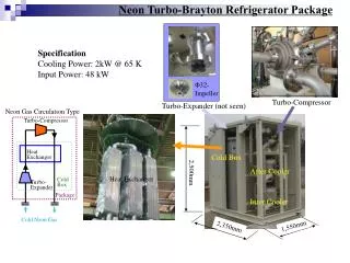
Radial Compressor. Example of a Slider Crank By, Yee Meng Yap, Corey Shipman, and Nicole Cannon. Abstract.

E N D
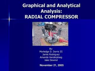
Radial Compressor Example of a Slider Crank By, Yee Meng Yap, Corey Shipman, and Nicole Cannon
Abstract • Our mechanism is comprised of a series of three redundant slider-crank assemblies. The function of this mechanism is to force a gas into a tank in which pressure can be built up and stored for later use. It is able to perform this function by having a motor driven shaft which controls the linear stroke motion and drives the three pistons. This causes the gas to be pulled into the tank. The pressurized gas can then be utilized as a means of energy to perform work such as powering an air tool or filling a tire. From our evaluation of the radial compressor, the results were that our numbers correspond with the numbers generated by the computer model. Our results also support the function of the mechanism.
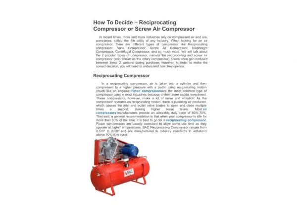
Introduction The radial compressor in question will be used to perform duties of a typical air compressor, such as: • Powering pneumatic systems on an aircraft • Operation of pneumatic tooling • Tire inflation • Pressurized paint sprayers • Tank systems • Beverage Dispensing
Analysis • Degrees of Freedom: • Links=8 • Type 1 Joints=10 • Type 2 Joints=0 • Ground=1 • m=3(L1-1)-2(L2)= 1 Degree of Freedom • Grashof? • L = 6.08 • S = 0 • P = 6 (Changes) • Q = 1 • S+L<P+Q • Yes, Grashof
Results • We have found that our rotary compressor has one degree of freedom controlled by our input angle of theta two. • Because we have found that it is a Grashof mechanism it will not seize. This has also been proven with our working model. • The velocity of the piston graph follows a negative sine function while the acceleration of the piston graph properly shows a negative cosine function, proving differentiation.
Results • After carefully examining our charted data we found that between the working model and calculated values we have less than one percent error. We found this by comparing our maximum piston velocities from both charts: • Working Model: 127 in/sec • Theoretical: 126 in/sec
Critical Parameters • The critical parameters consist of: • Stroke length • Frictionless • Velocity of the input crank • Cylinder and head diameter • Size of intake and exhaust valves • Material composition of the compressor All of these factors contribute to the proper functioning of the compressor.
Animation of Slider • Our working model animation is included on the project CD and is saved as “Model_1”. • Sorry for the inconvenience, we could not get our working model to work with power point.
Conclusion • Once again our mechanism is successful in completing a full rotation, it is controlled by one degree of freedom, and has a maximum piston velocity of approximately 127 in/sec. Also, our maximum piston acceleration is approximately 13,194 in/sec^2. • Our sources of error could be caused by conversions, significant figures, and other areas of human error. This could be improved by minimizing conversions such as carrying through one system of measurement, using more significant figures, and performing extended cross checking of calculations. • We could improve our mechanism by following industry standards of a shorter stroke and shorter piston length. This will allow us to increase speed and efficiency by decreasing friction.
Resources • Norton, R.L., Design of Machinery, Third Edition, McGraw-Hill, New York, 2004.