Download
1 / 12
301 likes | 2.15k Views
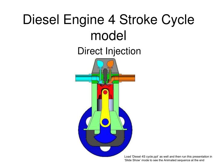
Diesel Engine 4 Stroke Cycle model. Direct Injection. Load ‘Diesel 4S cycle.ppt’ as well and then run this presentation in ‘Slide Show’ mode to see the Animated sequence at the end. 4 STROKE DIESEL ENGINE. Direct Injection. Geoff. Bootle. GTC UK 2009.

E N D
Diesel Engine 4 Stroke Cycle model Direct Injection Load ‘Diesel 4S cycle.ppt’ as well and then run this presentation in ‘Slide Show’ mode to see the Animated sequence at the end
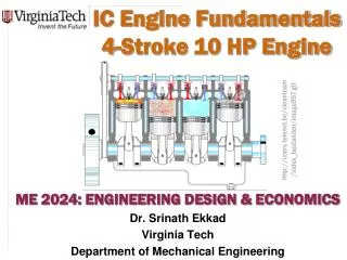
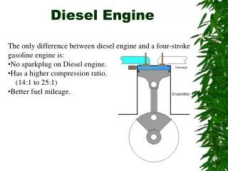
4 STROKE DIESEL ENGINE DirectInjection Geoff. Bootle. GTC UK 2009 • This is a simplified model of a single cylinder Diesel engine to show the principal parts, their relationships to each other and how the engine works. • Is not based on any real engine, but is generally representative of real engines. Most real engines are made up of several of this unit sharing a single flywheel and cam shaft drive e.g. Three, four and six cylinder engines. • Many minor details and some components are left out for clarity, for example the bearings, exhaust pipe silencer, air intake filter and the fuel injection pump.
THE CONSTRUCTION OF THE ENGINE Inside the solid body of the Engine are a number of fast moving parts Cam-shafts Moving parts Crank-shaft Cam Shaft Drive. The cam-shaft drive arrangement is simply represented by a box. In reality there would be a chain drive or a gear train between the crank-shaft and the cam-shafts. Bolts and fixings omitted for clarity
The Names of the Main Moving parts Piston Cam-Shafts Valve Spring Piston Ring Valves Gudgeon Pin Connecting Rod Crank-Shaft Fly- Wheel Bolts and fixings omitted for clarity
Some stationary parts Fuel Injector Cylinder Head Cover Cylinder Head Timing Case Sump (holds lubricating oil) Engine block Bolts and fixings are omitted for clarity
Cylinder Head, Cylinder and Piston The Cylinder Head sits on the top of the Block to close off the top of the Cylinder. It also carries the Valves, Fuel Injector and the Inlet and Exhaust passages Piston, a cylindrical part made to be a close, but free running, fit in the Cylinder of the Block. The Piston Rings fit in grooves on the Piston. They seal the Piston to be ‘gas tight’ in the Cylinder of the Block Cylinder, a large round hole bored straight and parallel through the Block Block, a large strong lump of metal that is the main structural member of the engine Bolts and fixings are omitted for clarity
PISTON, CRANK SHAFT & FLY-WHEEL • The Connecting Rod is inserted into a large recess in the bottom of the Piston • The Piston is attached to swivel on the ‘little end’ of the Connecting Rod by the Gudgeon Pin through the side of the Piston. • The ‘Big end’ of Connecting Rod fits onto the ‘throw’ of the Crank Shaft. (this end is usually split in half and bolted together for assembly purposes) • The Connecting Rod connects the linear ‘up and down’ motion of the Piston within the Cylinder with the circular rotary motion of the Crank Shaft. • The Fly-Wheel is attached to the end of the Crank-Shaft and serves to store the pulses of energy from the Power Strokes, delivering energy to the other 3 strokes, and power to whatever the engine is driving. Piston Gudgeon pin ‘Little End’ Connecting Rod ‘Big End’ ‘Throw’ Fly-Wheel Crank Shaft
VALVES One set of a Cam and a Valve controls the Inlet flow of fresh air into the Cylinder. The other set controls the burnt Exhaust Gases out of the Cylinder. Both these Valves are spring loaded to shut and seal the Cylinder during the Compression and Power strokes. They open into the Cylinder, so that they are held closed by the high pressures during the Compression and Power strokes. Bump, or lobe, on the Cam pushes the Valve open during part of the rotation of the Cam Exhaust Cam & Valve Spring Inlet Cam & Valve Inlet Passage Exhaust Passage
INJECTOR • The Fuel Injector is connected to a high pressure pump that is not illustrated. • It sprays a small amount of diesel fuel into the Cylinder at the end of the Compression Stroke and beginning of the Power Stroke. • The fuel is sprayed through several very small holes at very high pressure in order to form a fine mist of droplets of fuel that will ignite easily and burn quickly in the hot air. Nozzle tip with several small holes for fuel spray
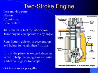
The 4 Stroke COMBUSTION CYCLE • The Diesel Engine 4 Stroke cycle consists of four distinct stages carried out whilst the engine Crank Shaft does two complete turns (or as we say, two revolutions). • The Cams rotate once every two turns of the Crank Shaft, i.e. once per complete 4 stroke cycle. • A ‘stroke’ is a movement of the Piston from one end of the Cylinder to the other end. 1st Stroke - INDUCTION. Fresh air is drawn into the Cylinder through the open Inlet Valve by the Piston descending. The Inlet Valve closes when the Piston reaches bottom of Cylinder, trapping the fresh air in the Cylinder. 2nd Stroke - COMPRESSION. The Air is squeezed as the Piston rises, reaching about 40 bar pressure. The air gets very hot (about 700° C) because of the work done to it by the Piston. Diesel fuel is started to be Injected into the Cylinder as the Piston gets near to the top. 3rd Stroke - POWER. Fuel is injected into the Cylinder for a short while as the Piston is near the top. The fuel spray ignites and burns in the hot air, creating even higher pressures and temperatures in the cylinder. The pressure of the hot gases push the Piston down, delivering power to the crank-shaft and fly wheel. 4th Stroke - EXHAUST. The Exhaust Valve opens and the rising Piston pushes the burnt gases out of the Cylinder. When the Piston gets near the top the Exhaust Valve closes and the Inlet Valve opens, ready to draw fresh air in again.
ANIMATION • Click here to run the animated Diesel engine combustion sequence. (this link will only work if you run the presentation in ‘Slide Show’ mode with ‘Diesel 4S cycle.ppt in the same directory as this file)