Download
1 / 37
380 likes | 530 Views
The Level 0 Pixel Trigger System for the ALICE experiment: implementation, testing and commissioning. Gianluca Aglieri Rinella 1 On behalf of the ALICE Silicon Pixel Detector Team 1 CERN, European Organization for Nuclear Research. Outline. ALICE Silicon Pixel Detector Detector modules

E N D
The Level 0 Pixel Trigger System for the ALICE experiment: implementation, testing and commissioning Gianluca Aglieri Rinella1 On behalf of the ALICE Silicon Pixel Detector Team 1CERN, European Organization for Nuclear Research TWEPP 2008 gianluca.aglieri.rinella@cern.ch
Outline • ALICE Silicon Pixel Detector • Detector modules • Fast-OR signals • Pixel Trigger System • Description • Features • Tests and qualification • Commissioning • First operation TWEPP 2008 gianluca.aglieri.rinella@cern.ch
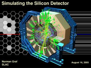
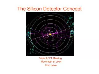
Time Projection Chamber Inner Tracking System Silicon Strip detector Silicon Drift detector Silicon Pixel Detector The ALICE experiment at LHC L3 solenoid magnet • Heavy ions collisions • Quark gluon plasma • Proton-proton collisions • pt ~ 0.6 GeV/c TWEPP 2008 gianluca.aglieri.rinella@cern.ch
39 mm 76 mm z 400 mm Silicon Pixel Detector • 120 detector modules (half staves) TWEPP 2008 gianluca.aglieri.rinella@cern.ch
SPD half stave • Each half stave (120): • Si pixel sensors (pixel size 425x50 um2) • 10 readout pixel chips (32x256=8192 pixels) • 10 MHz • Readout Multi Chip Module • 40 MHz • Provides 10 MHz to pixel chips Silicon Pixel Detector half stave 800 Mb/s Readout MCM Half stave 141 mm Sensor Sensor Pixel chips TWEPP 2008 gianluca.aglieri.rinella@cern.ch
Fast-OR signals SPD Half Stave Readout MCM Half stave 141 mm Sensor 1 Sensor Pixel chips • Pixel chip prompt Fast-OR • Active if at least one pixel hit in the chip matrix • 10 on each of 120 optical links (1200) • Transmitted every 100 ns • Low latency pad detector 1200 pads of 13x14 mm2 TWEPP 2008 gianluca.aglieri.rinella@cern.ch
Pixel Trigger System To DAQ 1200 bits @ 10 MHz Optical splitters Fast-OR extraction Processing CTP 120 G-Link Pixel Trigger electronics 225 ns 25 ns 350 ns 200 ns 800 ns • Overall latency: 800 ns • Space occupancy (1 crate) • Bottleneck: data deserialization and Fast-OR extraction • Processing time < 25 ns TWEPP 2008 gianluca.aglieri.rinella@cern.ch
12 4 160 mm Zarlink Zarlink Virtex4 Virtex4 86 mm Zarlink Virtex4 Zarlink Zarlink Virtex4 Virtex4 Pixel Trigger system electronics • 9U VME size processing board (BRAIN) • Main processing FPGA (960 user I/O pins, 1513 BGA) • 2x5 receiver boards (OPTIN) connected as mezzanine boards 400 mm • High speed optical interfaces • Alice Detector Data Link • Timing Trigger Large I/O Virtex4 Optical TxRx 360 mm • Data flow parallelism (~1000 lines) • 800 impedance matched lines • Digitally Controlled Impedance • Double Data Rate TTCRx Virtex4 USB DDL SIU JTAG TWEPP 2008 gianluca.aglieri.rinella@cern.ch
OPTIN receiver board • 12 channels • Parallel optical receiver module • 12 closely packed G-link deserializer ASICs TWEPP 2008 gianluca.aglieri.rinella@cern.ch
OPTIN boards Optical fan-in cable Processing FPGA DDL SIU 400 mm Control FPGA BRAIN and OPTIN boards TWEPP 2008 gianluca.aglieri.rinella@cern.ch
Pixel Trigger system crate TWEPP 2008 gianluca.aglieri.rinella@cern.ch
Interconnection test and power consumption • Electrical interconnects • Full JTAG testing • Dedicated tests for • lines non accessible by JTAG • high speed differential lines • Heat sinks on all regulators and deserializers • Peak board temperature: 45 °C (measured) • Peak junction temperature: 72 °C (thermal model) • Currents overestimated in design phase • Thermal model was too conservative TWEPP 2008 gianluca.aglieri.rinella@cern.ch
<Dt>=3 ns s = 1 ns Clock distribution • Measurement of phase distribution • Processing FPGA clock • Phase correction in order to place it at the centre of the distribution • Digital Clock Management • Measured signal propagation delay • Design: 7.8 ns/m • Measured: 6.95 ns/m TWEPP 2008 gianluca.aglieri.rinella@cern.ch
POFM Virtex Optical link BER tests • Full Fast OR data path Bit Error Rate test • 12 channels in parallel, each OPTIN tested sequentially • Pseudo random data • Link optical power: -18.5 dBm, 0.5 dBm margin 12 16 PRBS GOL 1x16 splitter DDR 10 MCM HW Emulator 60 Attenuator counter TWEPP 2008 gianluca.aglieri.rinella@cern.ch
POFM POFM POFM POFM POFM Virtex Virtex Virtex Virtex Virtex Fast OR data path integrity • Fast OR dedicated lines (600) Bit Error Rate test • 10 OPTIN boards, 120 channels simultaneously running • On board generation of User Defined data functionality (pseudo random sequences) • Duration: 15 hrs • Nbits = 6.48·1014 • Errors = 0 • BER < 7.1·10-15 (99% c.l.) 10·60 DDR 10 counters TWEPP 2008 gianluca.aglieri.rinella@cern.ch
Pixel Trigger system control • Custom control interface • ALICE Detector Data Link • On board PCI like bus • CONTROL FPGA acts as bus master and bridge to DDL • Reliability • Transaction acknowledgement • Parity checking • Error recovery PROC CONTROL SRAM DDL SIU • Read/write test pseudo-random data • Typical duration: 15 mins, ~6·108 bits exchanged, 0 errors • Longest: 12 hrs, ~ 3·1010 bits, 0 errors • See poster by Cesar Torcato Matos TWEPP 2008 gianluca.aglieri.rinella@cern.ch
733 ns Latency measurement Test pulse -> PIT output -> • Laboratory measurement • In ALICE • 768 ns (best case) • 793 ns (realignment) TWEPP 2008 gianluca.aglieri.rinella@cern.ch
Installation in ALICE experiment TTC 107.6±0.15 m Clk Serial C.R. 60 C side A side 36.6±0.2 m Data Central Trigger Processor Optical splitters 38.5±0.2 m LTU PIT main outputs L0 in TTC TWEPP 2008 gianluca.aglieri.rinella@cern.ch
3 0 FO(n-1) 1 Fb(n-1) 2 3 0 FO(n) 1 Fb(n) 2 3 0 FO(n+1) 1 Fb(n+1) 2 0 FO(n-1) 1 Fb(n-1) 2 3 0 FO(n) 1 Fb(n) 2 3 0 FO(n+1) 1 Fb(n+1) 2 3 3 0 FO(n-1) 1 Fb(n-1) 2 3 0 FO(n) 1 Fb(n) 2 3 0 FO(n+1) 1 Fb(n+1) 2 Synchronization BC clock HS i HS j HS k • 40 MHz clocks aligned by equalizing fibers length • 10 MHz clock phases aligned by broadcast signal on TTC • One clock period uncertainty left -> Measure relative phases • Measure arrival time of trigger feedback TWEPP 2008 gianluca.aglieri.rinella@cern.ch
OPTIN receiver board channel Snapshot Extraction Masking Delay Rx data FO FO FO 10 16 ODDR FO 10 FO Strobe 5 Framing User defined FO UDFO Rx cntrl Feedback Phase measurement Counters PIT Timer • Trigger feedback arrival clock period is time stamped • Discrete delay can be added to compensate for misalignments • Automatic driver function to measure latencies and set delay TWEPP 2008 gianluca.aglieri.rinella@cern.ch
3 0 FO 1 Fb 2 3 0 FO 1 L1 FB 2 3 0 FO 1 Fb(n+1) 2 3 3 0 FO 0 FO 1 Fb 1 Fb 2 2 3 3 0 FO 0 FO 1 L1 FB 1 L1 FB 2 2 3 3 0 FO 0 FO 1 Fb(n+1) 1 Fb(n+1) 2 2 3 0 FO 1 Fb 2 3 0 FO 1 L1 FB 2 3 0 FO 1 Fb(n+1) 2 0 FO 0 FO 0 FO 0 FO 1 Fb 1 Fb 1 Fb 1 Fb 2 2 2 2 3 3 3 3 0 FO 0 FO 0 FO 0 FO 1 L1 FB 1 L1 FB 1 L1 FB 1 L1 FB 2 2 2 2 3 3 3 3 0 FO 0 FO 0 FO 0 FO 1 Fb(n+1) 1 Fb(n+1) 1 Fb(n+1) 1 Fb(n+1) 2 2 2 2 3 3 3 3 Frame alignment A side C side TWEPP 2008 gianluca.aglieri.rinella@cern.ch
Cosmic radiation in the cavern • Pixel trigger used for cosmic data taking • SPD only • ALICE (ITS + TPC) • Alignment data • 65000 events 3 clusters in SPD • 35000 events 4 clusters in SPD • Showers TWEPP 2008 gianluca.aglieri.rinella@cern.ch
Cosmic data clusters • Rate 0.09 Hz – 0.12 Hz • Well in agreement with Monte Carlo and measured flux in the cavern • Cluster distribution • 99.5 % of events with correct cluster distribution TWEPP 2008 gianluca.aglieri.rinella@cern.ch
Summary • The ALICE Pixel Trigger system allows to include the prompt Fast-OR outputs of the Silicon Pixel Detector in the Level 0 trigger decision • ALICE is the only LHC experiment including the vertex detector in the first trigger decision from startup • The Pixel Trigger system • Installed and operational • Board level and system level challenging requirements • Highly compact solution including original developments • Commissioning and first operation TWEPP 2008 gianluca.aglieri.rinella@cern.ch
LHC beam injection tests August 2008: the ALICE experiment detected “LHC related particles” during the very first injection tests SPD was recording data and self-triggering with the Pixel Trigger system TWEPP 2008 gianluca.aglieri.rinella@cern.ch
References References: • G. Aglieri Rinella et al., “The Level 0 Pixel Trigger system for the ALICE experiment”, Journal of Instrumentation JINST 2P01007 and Proceedings of the 12th Workshop on Electronics for LHC and Future Experiments, LECC06, September 2006, Valencia, Spain • A. Kluge et al., “The ALICE Silicon Pixel Detector”, Nuclear Instruments and Methods A, Volume 582, Issue 3, 1 December 2007, Pages 728-732 • ALICE collaboration, “ALICE physics Performance Report”, CERN-LHCC-2003-049, J. Phys., G30 (2004) 1517-1763 • J. Conrad et al., “Minimum Bias Triggers in Proton-Proton collisions with the VZERO and Silicon Pixel Detectors”, ALICE Internal note, ALICE-INT-2005-025, 19/10/2005 TWEPP 2008 gianluca.aglieri.rinella@cern.ch
Spare slides TWEPP 2008 gianluca.aglieri.rinella@cern.ch
SPD detector TWEPP 2008 gianluca.aglieri.rinella@cern.ch
Triggering with SPD Fast-OR • Extract and process Fast-OR signals • Generate input for the Level 0 (fastest) trigger decision • 1200 Fast-OR signals on 120 optical links every 100 ns • Proton-proton • Minimum bias • High multiplicity studies • Topological selection (jets) • Heavy ions • Selection of impact parameter • Algorithms • Topology (Global OR, Vertex) • Multiplicity • Boolean functions of 1200 Fast-OR bits TWEPP 2008 gianluca.aglieri.rinella@cern.ch
Trigger algorithms • Combinational (boolean AND/OR) functions of 1200 Fast-OR bits • Occupancy (multiplicity) • Coincidence trigger (topology) • Not possible: iterative algorithms on data set Example: vertex trigger • Pseudo-Tracklet: one chip hit on inner and one on outer layer, in line with region +/-10 cm around vertex • Chip map for pixel trigger electronics calculated from simulation: (L11,L21), (L12, L22), … , (L1n, L2n) • FPGA looks for at least 1 out of 11000 pseudo-tracklets • Processing time 12.4 ns (Xilinx ISE) • 4% of FPGA resources (Xilinx ISE) • FPGA counts how many out of 11000 tracklets are present • ~27 ns processing time (Xilinx ISE) • 5% of FPGA resources (Xilinx ISE) TWEPP 2008 gianluca.aglieri.rinella@cern.ch
Multiplicity trigger Domenico Elia TWEPP 2008 gianluca.aglieri.rinella@cern.ch
ALICE trigger parameters TWEPP 2008 gianluca.aglieri.rinella@cern.ch
Angular resolution TWEPP 2008 gianluca.aglieri.rinella@cern.ch
Radiation effects • Radiation Results of the SER Test of Actel, Xilinx and Altera FPGA instances, iROC report, 2004 • Failure In Time (FIT) := errors in 109 hours with neutron flux of 14 cm-2hr-1 • SEFI: Single Event Functional Interrupt • SEU: Single Event Upset (configuration) • Neutron max fluence: 2.0 • 108 cm-2 (10 y) • Morsch, Pastircak, Radiation in ALICE Detectors and Electronic Racks, ALICE-INT-2002-28 • Central Trigger Processor using SRAM based ALTERA Cyclone EP1C20 TWEPP 2008 gianluca.aglieri.rinella@cern.ch
10010110 10010110 Developments • Advanced 12-channel parallel optical fiber receiver modules • Devices customized by Zarlink • 1310 nm, single mode • Experimentally validated • Space saving • G-Link protocol deserializers on programmable hardware • Implemented and tested with advanced FPGAs • Not fulfilling latency requirement • Dedicated deserializer ASIC TWEPP 2008 gianluca.aglieri.rinella@cern.ch
Latencies of processes • Serialization, deserialization, processing latency • Hardware emulator of the Silicon Pixel Detector as data source • Overall latency: 800 ns 215 ns TWEPP 2008 gianluca.aglieri.rinella@cern.ch
Control and configuration • Status monitoring and control on ALICE DDL communication layer • User selection of different processing algorithms • Download of configuration file into local SRAM memory • Reconfiguration of the processing FPGA • Interfaces to several ALICE subsystems Experiment Control Central Trigger Processor Control Silicon Pixel Detector Control DDL Pixel Trigger servers (control room) TWEPP 2008 gianluca.aglieri.rinella@cern.ch