Download
1 / 6
70 likes | 311 Views
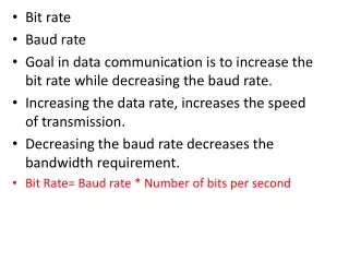
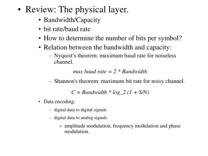
Review: The physical layer. Bandwidth/Capacity bit rate/baud rate How to determine the number of bits per symbol? Relation between the bandwidth and capacity: Nyquist’s theorem: maximum baud rate for noiseless channel. max baud rate = 2 * Bandwidth

E N D
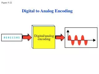
Review: The physical layer. • Bandwidth/Capacity • bit rate/baud rate • How to determine the number of bits per symbol? • Relation between the bandwidth and capacity: • Nyquist’s theorem: maximum baud rate for noiseless channel. max baud rate = 2 * Bandwidth • Shannon's theorem: maximum bit rate for noisy channel. C = Bandwidth * log_2 (1 + S/N) • Data encoding: • digital data to digital signals • digital data to analog signals • amplitude modulation, frequency modulation and phase modulation.
Simplex/half-duplex/duplex communication • Multiplexing: when it is needed? • Time Division Multiplexing, Frequency division Multiplexing, Code division multiplexing.
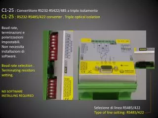
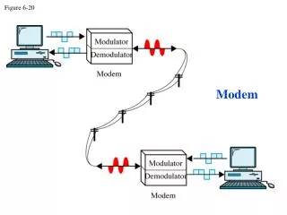
A physical layer protocol: RS-232-C. • Four components: • mechanical interface • electrical interface • functional interface • procedureal interface • Terminology: • DTE (data terminal equipment): computer • DCE (data circuit-terminating equipment): modem
mechanical interface: • 25-pin connector • 47.04+-0.13mm wide • top row 1-13 • bottom row 14-25 ....., • cable 15m • electrical interface: • 1: < -3V • 0: > 4V • bit rate: up to 20kbps
functional interface: which circuit should connect to which pin (Fig 2-21). • 1: protective ground • 2: transmit • 3: receive • 4: request to send • 5: clear to send • 6: data set ready • 7: common return • 8: carrier detect • 20: data terminal ready (1) (2) (3) (4) (5) (6) (7) (8) (20)
procedural interface: legal sequence of events. • Example: • DTE requests to send, • DCE clear to send.