Download
1 / 16
160 likes | 259 Views
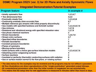
This study explores plasma dynamics in fusion systems utilizing mirror devices, focusing on neutron generation concepts, power balance, local balance schemes, radiation losses, numerical approximations, and optimal parameters. The research delves into particle kinetics, Fokker-Planck equations, boundary conditions, and numerical calculations for plasma behavior in mirror fusion systems.

E N D
PLASMA KINETICS MODELS FOR FUSION SYSTEMS BASED ON THE AXIALLY-SYMMETRIC MIRROR DEVICES A.Yu. Chirkov1), S.V. Ryzhkov1), P.A. Bagryansky2), A.V. Anikeev2) 1)Bauman Moscow State Technical University, Moscow, Russia 2)BudkerInstitute of Nuclear Physics, Novosibirsk, Russia
Simple mirror geometry with long central solenoid Injection of energetic neutrals Neutron generator concept: T ~ 10..20 keV, n~ 1019m–3, a~ 1 m, L~ 10 m, B ~ 1..2 Tin center solenoid, ~ 20 T in mirrors, fast particle energy~ 100..250 keV, Pn Pinj
The power balance scheme Local balance Plasma amplification factor
1.6 1.5 2 ––––– fit – - – - Elwert - - - - - Gould 3 g 1.4 1 1.3 1.2 1.1 1 10 100 103 104 105 1 Te, eV Radiation losses Electron – ion bremsstrahlung mec2 = 511 keV Electron energy losses during slowing down on ions CE= 0.5772... Pei – correction to the Born approximation – forTe ~ 1 keV[Gould] Integral Gaunt factor: Approximation taking into account Gaunt factor for low temperatures: Gaunt factors for low temperatures. Approximations ofB: 1 – formula correspondsg 1 atTe 0; 2 – ggElwert atTe 0; 3 – by Gould
Electron – electron bremsstrahlung CF= (5/9)(44–32) 8 CE= 0.5772... Approximations of numerical results
Trrel Ps/Ps0 1 0 1 – Te = Ti = 30 keV 2 – 50 keV 3 – 70 keV 4 – 90 keV a = 2 m, Rw = 0.7, Bext = 7 T 0.2 –––– Trubnikov – – – Trubnikov + relativistic corr. - - - - Tamor, Te < 100 keV – - – - Tamor, Te = 100–1000 keV – - - – Kukushkin, et al. 0.18 0.16 1 0.14 0.12 4 0.1 3 0.08 0 . 1 2 0.06 1 0.04 0.02 0 10–2 0 0.2 0.4 0.6 0.8 0 1 10–3 1 0 1 0 0 1 0 0 0 Te, keV Synchrotron radiation losses Emission in unity volume of the plasma: Losses from plasma volume (Trubnikov): Output factor: – Trubnikov Output factors ata = 2 m, Rw = 0.7, Bext = 7 T, 0 = 0.1 (upper curves) and0 = 0.5 (down) – relativistic correction [Tamor] Generalized Trubnikov’sformula for non-uniformplasma[Kukushkin et al., 2008]: Output factor vs0ata = 2 m, Rw = 0.7, Bext = 7 T, Te = Ti = 30 keV (1), 50 (2), 70 (3),and 90 keV (4)
Fast particle kinetics b Proton slow-down rate (a) and cross section (b) for interactionwith electrons (- - - - -), deuterium ions (–––––) and helium-3 ions (– - – - –): 1, 2 – Coulomb collisions,3 – nuclear elastic scattering D–T reactionand slow-down cross sections ratio for tritium ions in the deuterium plasma with Ti = Te = T
Some estimations High-energy approximation: MW/m3 m3/s keV keV keV Optimal parameters: T 10 keV, Einj 100 keV, Pn Pinj ~ 4MW/m3
The Fokker – Planck equation Boundary conditions: In the loss region Quasi isotropicvelocity distribution function:
Numerical scheme Scales and dimensionless variables: Dimensionless equation (symbols “~”are not shown):
Numerical scheme Greed: Finite difference equations: Matrix form:
Examples of numerical calculations Velocity distribution function of tritium ions and its contours at time moments after injection swich ont = 0.1s (а), 0.3s (b) и 10s (c). Deuterium density nD = 3.31019 м–3, energy of injected particles 250 keV, injection angle 455, injection power 2 MW/m3, Ti = Te = 20 keV, = 10 keV, slow-down times= 4.5 s, transversal loss time = s
0 0 . . 1 3 0 0 . 3 0 . 1 2 2 0 . 0 8 2 . 8 WL /W0 0 . 2 0 . 0 0 8 p/p0 0 . 0 6 2 . 4 n/n0 /s . 0 . 1 0 0 0 4 0 . 0 4 2 . 0 0 . 0 0 2 0 1 . 6 5 5 1 0 1 0 1 5 1 5 2 0 2 0 T, keV T, keV Role of particles in D–T fusion mirror systems Relative pressure and density of alphas in D–T plasma (D:T = 1:1): –––––– isotropic plasma (no loss cone) – – – – mirror plasma with loss cone n0 = nD + nT = 2nDp0 = pD = pT Energy losses (WL) due to the scattering into the loss cone and corresponding energy loss time () of alphas in D–T mirror plasma W0 is total initial energy of alphas (3.5 MeV/particle) s is slowdown time
Parameters of mirror fusion systems: Neutron generator and reactors with D–T and D–3He fuels