Download

1 / 17
170 likes | 177 Views
CFD-based Liquid Flow Calculations for Modular Sample Systems. John J. Wawrowski Swagelok Solon, Ohio. IFPAC 2004 Arlington, Virginia January 12-15, 2004. Agenda. Review of Previous Work Flow Testing Description Flow Testing Results Is a larger standard required?

E N D
CFD-based Liquid Flow Calculations for Modular Sample Systems John J. Wawrowski Swagelok Solon, Ohio IFPAC 2004 Arlington, Virginia January 12-15, 2004
Agenda • Review of Previous Work • Flow Testing Description • Flow Testing Results • Is a larger standard required? • Important Considerations • Conclusions
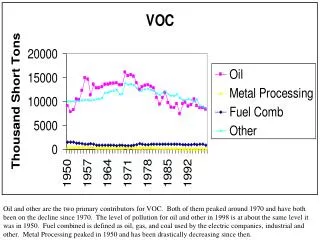
Previous Work Studied • The flow capacity (Cv) of a three-position Swagelok MPC system • The effects of using different surface-mount components on the total system Cv • An analytical method for predicting the total system Cv • The effect of the fluid type on the pressure drop through a substrate flow component • The pressure required for a liquid sample to flow through a three-position Swagelok MPC system
Previous Work Results • Created and validated a mathematical model for predicting flow capacity of a Swagelok MPC system • The surface-mount component has the largest effect on total system Cv • Developed a valid equation for predicting pressure to drive liquids • Based on kinematic viscosity • MPC requires minimal driving pressure
Check Valve Cv = 0.9 Toggle Valve Cv = 0.11 Filter Metering Valve Cv = 0.03 Pneumatic Valve Cv = 0.07 Previous Work System Cv changes based on surface-mount components Total system Cv: 1/Cvtotal2 = Σ (1/Cvi)2
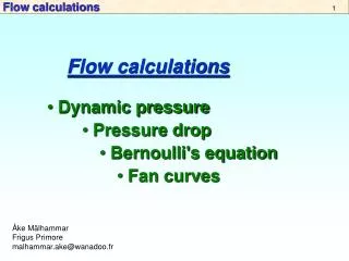
Previous WorkEffects of fluid type on required driving pressure • For liquids with similar kinematic viscosities (υ = μ/ρ): ΔPfluid / ΔPwater = (1/SGfluid) x (mass flow rate of fluid/mass flow rate of water)2 • For liquids with different kinematic viscosity (i.e. motor oil): ΔPfluid / ΔPwater = (υfluid / υwater).5
Pressure to Drive Liquids300 ml/min through 3-position MPC system
New Testing • Re-tested original three-position system • Nine-position system • Stream Selector valve included • Ethylene-Glycol and 10W-30 Oil • Determine pressure required to achieve 300 cc/min • Tested by an independent third party
Preliminary ResultsDrive pressure to achieve 300 cc/min • Ethylene Glycol • 3-position system: 10 psig • 9-position system: 20+ psig • Depending on metering valve position • 10W-30 Oil • 3-position system: 30 psig • 9-position system: 40+ psig
New Standard Needed? • Component with the lowest Cv has the greatest affect on the total system Cv • Surface mount components on the market have the same Cv’s as their traditional configurations • Stream Select Valve • Needle Valves • Filters • Check and Relief Valves • 0.1 is typical
Important Considerations • Regardless of the size of the flow passages, all sample systems will eventually need to be maintained • Plugging • Corrosion • Leakage • You should choose a substrate design that facilitates fast, easy maintenance or expansion • Replace or add components without disassembly or removal of the entire system • Convenient access to internal components • Fewest number of o-rings • Ease the burden on instrument and maintenance technicians • Lower cost of spare parts
Wrap-Up • Please visit us in Booth 315/317 • Automated System Demonstration • pH and conductivity sensor array • Laboratory GC carrier gas metering system • New surface-mount components • Regulator • Solenoid Valve • pH and conductivity sensors • Discuss the topics presented