Download
1 / 40
400 likes | 405 Views
This article discusses the technical challenges and strategies for powering the CLIC accelerator, including klystron modulators, pulse parameters, system bandwidth, power consumption, and modular approaches.

E N D
TE EPC Powering CLIC Strategies and Technical Issues Daniel Siemaszko, Serge Pittet, David Nisbet CERN, Technology Department (TE) Electronic Power Converter Group (EPC) Low Power Converters (LPC) CH-1211 Genève 23 24.09.2010
OUTLINE TE EPC • Technical description of main issues related to CLIC, namely: • Klystron modulators for drive beam linac. • Powering the main linac. • Machine availability. • Next steps • For CLIC CDR. • For CLIC TDR. Daniel Siemaszko, Serge Pittet, David Nisbet, EDMS 1095040
TE EPC Drive beam injection Daniel Siemaszko, Serge Pittet, David Nisbet, EDMS 1095040
Klystron parameters TE EPC Up to now, there is no klystron modulators that can fulfill such requirements, need for development. Daniel Siemaszko, Serge Pittet, David Nisbet, EDMS 1095040
Pulse parameters TE EPC The perfect pulse (required) The real world Daniel Siemaszko, Serge Pittet, David Nisbet, EDMS 1095040
System and bandwidth TE EPC • Quality of RF is dependant on many inputs. • RF feed-forward control takes care of modulator harmonics, voltage droop and other systematic errors. • RF feed-back control takes care of other errors (eg temperature drift, calibration, etc) • At lower frequencies, precision is less important due to RF feedback • At higher frequencies, precision is less important due to natural machine filtering. • 10-5 pulse to pulse reproducibility precision required between 6kHz and 4MHz. Daniel Siemaszko, Serge Pittet, David Nisbet, EDMS 1095040
Klystron modulators TE EPC • Modulator requirements and characteristics • Flat-top is 190us (50% to 50%) Daniel Siemaszko, Serge Pittet, David Nisbet, EDMS 1095040
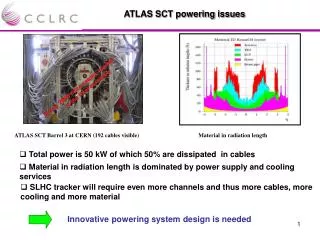
Power consumption TE EPC • A rise time and fall time of 20ms, and settling time of 30ms, is assumed. • Note that the baseline currently assumes 90% efficiency for modulator. This is realistic for energy conversion, but unrealistic if dynamics are considered. • Thus the power consumption is evaluated for a 15MW klystron assuming klystron efficiency of 65% (70%) and modulator efficiency of 90% (92%) and dynamic effects. • R&D required to reduce rise/fall times and settling times, to obtain >90% efficiency, and consume true constant power. • System level R&D for power management and grid effects when shutting down or failure modes of many modulators (the grid can only tolerate a gradual change at this power level). Daniel Siemaszko, Serge Pittet, David Nisbet, EDMS 1095040
Classic approach TE EPC • Pulse transformer: The pulse is generated at high current lower voltage at the primary side of the pulse transformer. 150kV is reached at the secondary side. • Switch: High voltage, high current solid state switch. • Storage capacitor: The pulsed power is collected by an intermediate storage capacitor before being transmitted through the switch. • Voltage droop compensation: Voltage compensator for the droop occurring in the storage capacitor during the pulse discharge. • Charger: Classical resonant topology for charging the capacitor. Daniel Siemaszko, Serge Pittet, David Nisbet, EDMS 1095040
CW and Pulsed Modulators TE EPC Pulse modulators at CERN. • LEP 4MW CW Modulator: 350 m3 • LINAC4 5MW Pulsed Modulator: 7 m3 Daniel Siemaszko, Serge Pittet, David Nisbet, EDMS 1095040
Modular approach (1) TE EPC • Modular approach based on a ‘classic’ modulator with charger, intermediate storage capacitor, pulse switch and pulse transformer. • Need to design a fast enough pulse transformer • Dimensioning of pulse transformer must take isolation voltage into account -> transformer volume ... Daniel Siemaszko, Serge Pittet, David Nisbet, EDMS 1095040
Modular approach (2) TE EPC • Modular approach based on medium frequency transformer and direct rectification including a charger and an output filter. • No intermediate energy storage -> direct conversion • Use of MF transformer allows space and cost reductions when compared to pulse transformer. • Passive components of the filter must be rated for full voltage and allow fast voltage transients. Could also be modular structure on each rectifier. • Very interesting solution but need for R&D, in particular concerning rise time, reproducibility and transformer design. Daniel Siemaszko, Serge Pittet, David Nisbet, EDMS 1095040
Space requirements TE EPC • With a first estimation, the modulators would require ~8 standard racks per klystron. • The two linacs are placed side by side every 3.1m (2.5km for the whole linac) . Daniel Siemaszko, Serge Pittet, David Nisbet, EDMS 1095040
Overview TE EPC • Cost, efficiency and reproducibility requirements are key parameters for the machine feasibility • Design for pulse-to-pulse reproducibility of 10-5 at 150kV is a significant issue -> significant R&D in characterisation, measurement and feedback techniques • Constant power consumption at modulator level, and power management strategies on a machine scale, will be required • Modulator redundancy important to ensure sufficient availability of such a large number of systems • Plenty of topics requiring further research! Daniel Siemaszko, Serge Pittet, David Nisbet, EDMS 1095040
TE EPC Main Linac Daniel Siemaszko, Serge Pittet, David Nisbet, EDMS 1095040
Main linac (two-beam accelerator) TE EPC • The main beam is accelerated by RF energy exchanger linking the drive beam which is sequentially decelerated. • For reaching 3TeV, the 50km long tunnel contains 48 accelerating sectors and need the powering of about 45’000 quadrupoles and 4’000 dipole correctors. • The power converters are located in a confined area, meaning strong restrictions on power dissipation and accessibility. • High radiations lead to the use of dedicated caverns along the tunnel. • Cabling aspects (number and power dissipation) does not allow individual powering. Daniel Siemaszko, Serge Pittet, David Nisbet, EDMS 1095040
Sequence of modules TE EPC • The module sequence along the tunnel is a composition of modules of type 1,2,3 or 4 each containing a quadrupole and module of type 0 without quadrupoles. • Two powering strategies, one for each beam is presented. • High density of quadrupoles in the first section, then the number of them decreases along the tunnel. Impact on the number of power converters with a factor 3. Daniel Siemaszko, Serge Pittet, David Nisbet, EDMS 1095040
Main beam quads powering TE EPC • Serial connection of converters approach, voltage sources with regulated output currents. (Converters ratings : 126A, 30V for types 1-2, 60V for types 3-4). • Failure tolerant operation if two consecutive magnets can share the same current. • Around nominal operation, flexibility in magnet currents is guaranteed. • Flexibility in magnet sequence requirement also guaranteed. • The second quadrant in the converters can be implemented with only dissipative components to dump the inductive energy during transients. Daniel Siemaszko, Serge Pittet, David Nisbet, EDMS 1095040
Power consumption TE EPC • The power consumption of the whole linac is not distributed linearly. There is a factor of three between the first accelerating sector and the last. • Total power consumption per linac: 7 MW. • The losses in the cables, meaning the dissipation to air reach 7 KW in the first sector (7.95W/m mean value along the tunnel, 19W/m maximal value ). Daniel Siemaszko, Serge Pittet, David Nisbet, EDMS 1095040
Drive beam requirements TE EPC • Field profile in nominal operation in the range of 69 to 6.9 T/m linearly distributed along each sector within the 860 quadrupole (meaning 120A-12A). • Flexibility requirements on the gradients as presented on the figure (ref. Adli) • Failure tolerant powering strategy is needed in order to prevent maintenance at each failure. • Failure tolerant scenarios must ensure a beam remittance within range defined by physics. • More than 20 failures can be tolerated in each accelerating sector if the current in failed magnets does not drop under 98% (ref. Adli). Daniel Siemaszko, Serge Pittet, David Nisbet, EDMS 1095040
Current profiles TE EPC • The Non linear distribution of currents in magnets is due to field saturation effect. • 120% flexibility has a increase in consumption of 10MW when compared to a 110% flexibility. • The maximal difference in currents between two consecutive magnets is 0.63A (0.36%). • It has been agreed to base power calculations on a 110% basis. Alexey Vorozhtsov, “Powered Magnets, DB Formation and Decelerator”, October 2010, IWLC. Daniel Siemaszko, Serge Pittet, David Nisbet, EDMS 1095040
Drive beam quads powering TE EPC • One big converter with serial connection of active trimmers approach. The main converter ratings depend on the number N of trimmers in series. • N=[10-60], depending on the position in the lattice. • Solution allows a serious reduction on cabling costs and power consumption. • Flexibility in magnet currents profile is guaranteed and a negative slope in current profile is reachable with only dissipative trimmers. • Flexibility on one magnet current guaranteed for calibration purpose. Daniel Siemaszko, Serge Pittet, David Nisbet, EDMS 1095040
Failure tolerant operation TE EPC • Trimming cables are implemented with serial diodes (only dissipative trimming). • When a failed trimmer is short-circuited, the diode does not allow the current magnet to fall lower than the following one. • Open circuit case affects all previous magnets. • Few seconds are needed for stabilising the currents in the remaining magnets. Imag4 = Imag5 after trimmer 4 failure Daniel Siemaszko, Serge Pittet, David Nisbet, EDMS 1095040
Reliability of the decelerator TE EPC • Reliability of solutions using trimmers depends on the reliability of the main converter. • (N+1) redundancy is achieved using a modular solution. The number of modules depends on current need for the magnets. • The whole lattice can be assembled with one type of modules only. • Power profile along the tunnel is divided into powering regions defining converter families. Daniel Siemaszko, Serge Pittet, David Nisbet, EDMS 1095040
Voltage ratings of the modules TE EPC • The rating of the module voltage and current that will construct the main converters has an impact on the power dissipation to air which has to be optimised. • At low voltage, the dissipation comes from the cables, at higher voltage, the dissipation comes from the trimmers. • An optimum is found at 220V for maximum power operation independently from the current ratings. Daniel Siemaszko, Serge Pittet, David Nisbet, EDMS 1095040
Current ratings of the modules TE EPC • The current rating of the modules has an impact on the number of implemented modules and the overrating in current of the whole decelerator. • An absolute optimum cannot be found as with the voltage so the current rating of the module is chosen as a divider or the maximum current rating (124A). Daniel Siemaszko, Serge Pittet, David Nisbet, EDMS 1095040
Trimmers distribution TE EPC • The distribution of trimmers in strings is not linear. It is constructed as a function of the main converter voltage. • The maximal power dissipated by a trimmer is 33W. • The overrating ratio is calculated as the opposite of the useful power over the installed power. Daniel Siemaszko, Serge Pittet, David Nisbet, EDMS 1095040
Power dissipation in the tunnel TE EPC • The dissipation to air is the sum of the cable dissipation and the trimmers • The choice of the midpoint (in terms of cabling from the caverns) has an impact on the mean power dissipation and its maximal value. • Maximal power dissipation can be reduced with the use of thicker cables at higher fields. Daniel Siemaszko, Serge Pittet, David Nisbet, EDMS 1095040
Main Linac power consumption TE EPC • The consumption if evaluated for the whole 48 sectors assuming 80% efficiency for the power converters. • The power dissipation to air has a mean value of 30W/m and an absolute maximal value of 80W/m. Daniel Siemaszko, Serge Pittet, David Nisbet, EDMS 1095040
Correctors and trimmers control TE EPC • MB correctors and DB trimmers controlled using FEAS (CLIC Front End Acq. Sys. with digital to analog converters and 100Hz read-out). • Fast control loop in the corrector (10kHz/precision 1%). • Slow control loop located over ground (1Hz), high precision (100ppm) allowed with temperature measurement and precise tuning stored in database. • RAD-HARD Trimmers placed close to the magnets with limited precision to 1% (still insuring a current precision of 100ppm in the magnet). Daniel Siemaszko, Serge Pittet, David Nisbet, EDMS 1095040
TE EPC Machine Availability Daniel Siemaszko, Serge Pittet, David Nisbet, EDMS 1095040
Reliability Hypothesis TE EPC • N+1 redundancy allows one failure of the modules in a power converter. The whole converter fails when two module failures occur. • A factor k of 5% is added for describing the converter failures that are not saved by redundancy. • The trimmers allow up to twenty failures. • Preventive maintenance days are scheduled for replacing failed modules and trimmers (14d). • Estimated repair time includes machine cool down and walking time in the tunnel (4h). Daniel Siemaszko, Serge Pittet, David Nisbet, EDMS 1095040
Composite MTBF model TE EPC • Failure rates m=MTBF-1 combined with the same association rules as impedances. • Reliability calculated as a function of failure rate and mean time between preventive maintenance. • Expected down time has a linear relationship to the energy to be reached. Daniel Siemaszko, Serge Pittet, David Nisbet, EDMS 1095040
Markov chains TE EPC • Each converter defined as a set of states with probability transitions after each time step R. • Failure probabilities defined as a function of failure rate and time step. • The failure probability of the whole system is a combination of all components probabilities. • In this case, after 200 days the probability of a system failure reaches 100% (obviously). Daniel Siemaszko, Serge Pittet, David Nisbet, EDMS 1095040
Poisson modelling TE EPC • Failure rates are assumed to be Independent Identically distributed exponential variables. • The expected number of failures is given as a function of horizon time (namely days between preventive maintenance) with an envelope corresponding to 95% probability. • Down time is a function of number of failure and MTTR (Mean time to repair) and considered the down time of the maintenance days. • An optimum is found between 150 and 200 days with an expected down time of 1.6%. Daniel Siemaszko, Serge Pittet, David Nisbet, EDMS 1095040
Optimisation and technical specs TE EPC • The parameters of the three presented models need to be refined to stick with reality, especially the mean time to repair and the scheduled preventive maintenance days. • Parameters like the failure rate and the rate of failure saved by redundancy are dependent on the hardware. Their optimisation goes through technical specifications and careful design considerations. • Previous hypothesis assume accurate crowbar control, easy replacement of modules and immunity against surges and explosions of a neighbour. Daniel Siemaszko, Serge Pittet, David Nisbet, EDMS 1095040
TE EPC Next steps Daniel Siemaszko, Serge Pittet, David Nisbet, EDMS 1095040
For the CDR TE EPC • We need to complete the magnets inventory (main beam injection complex, interaction point) • We would like, if possible, to push the magnet team toward a uniformisation of the needs in current in order to reduce power converter design costs and future spare management issues. If not for the CDR, then for the TDR. • We will go on our studies about availability models and coordinate this work with machine protection working group. Daniel Siemaszko, Serge Pittet, David Nisbet, EDMS 1095040
For the TDR TE EPC • The design of the drive beam klystron modulators is a crucial issue that will need development. • The power management, especially during machine abort must be carefully studied in terms of power losses and grid stability. • The decelerator structure needs to be validated with a prototype. A reduced scale system with 6 magnets and 5 trimmers will be built and fully tested in terms of dynamics and reliability. • The improvement of power converters reliability will be studied with a modular approach. Dynamics during failures will be carefully studied. Daniel Siemaszko, Serge Pittet, David Nisbet, EDMS 1095040
TE EPC Thank you for attention • References: • Powering the main linac implications, Daniel Siemaszko, Serge Pittet - EDMS 1075533 • Main beam magnets powering strategy Daniel Siemaszko, Serge Pittet - EDMS 1060595 • Powering strategy for the main beam quadrupoles in the main linac, Daniel Siemaszko, Serge Pittet - EDMS 1095022 • Drive beam magnets powering strategy Daniel Siemaszko, Serge Pittet - EDMS 1064316 • Failure tolerant operation and powering strategy for the drive beam quadrupoles, Eric Adli, Daniel Siemaszko - EDMS 1095023 • Reliability requirements for powering CLIC, Daniel Siemaszko - EDMS 1095024 • Drive beam RF injector, Daniel Siemaszko, David Nisbet - EDMS 1083575 • Existing pulsed power modulator topologies, Carlos De Almeida Martins – INDICO 87528 Daniel Siemaszko, Serge Pittet, David Nisbet, EDMS 1095040