Download
1 / 110
1.13k likes | 1.37k Views
Learn the basics of series and parallel circuits, including calculations and real-world applications. Understand the role of resistors, current, and voltage in circuit design.

E N D
Chapter Series and Parallel Circuits 23
Chapter Series and Parallel Circuits 23 In this chapter you will: • Distinguish among series circuits, parallel, and series-parallel combinations, and solve problems involving them. • Explain the function of fuses, circuit breakers, and ground-fault interrupters, and describe how ammeters and voltmeters are used in circuits.
Chapter Table of Contents 23 Chapter 23: Series and Parallel Circuits Section 23.1: Simple Circuits Section 23.2: Applications of Circuits
Section Simple Circuits 23.1 In this section you will: • Describe series and parallel circuits. • Calculate currents, voltage drops, and equivalent resistances in Simple Circuits.
Section Simple Circuits 23.1 Series Circuits • Although the connection may not immediately be clear to you, a mountain river can be used to model an electric circuit. • From its source high in the mountains, the river flows downhill to the plains below. • No matter which path the river takes, its change in elevation, from the mountaintop to the plain, is the same. • Some rivers flow downhill in a single stream.
Section Simple Circuits 23.1 Series Circuits • Other rivers may split into two or more smaller streams as they flow over a waterfall or through a series of rapids. • In this case, part of the river follows one path, while other parts of the river follow different paths. • No matter how many paths the river takes, however, the total amount of water flowing down the mountain remains unchanged. • In other words, the amount of water flowing downhill is not affected by the path it takes.
Section Simple Circuits 23.1 Series Circuits • How does the river shown in the figure model an electric circuit? • The distance that the river drops is similar to the potential difference in a circuit. • The amount of water flowing in the river is similar to current in a circuit. • Narrow rapids create resistance and are similar to resistors in a circuit.
Section Simple Circuits 23.1 Series Circuits • What part of a river is similar to a battery or a generator in an electric circuit? • The energy source needed to raise water to the top of the mountain is the Sun. • Solar energy evaporates water from lakes and seas leading to the formation of clouds that release rain or snow that falls on the mountaintops. • Continue to think about the mountain river model as you read about the current in electric circuits.
Section Simple Circuits 23.1 Series Circuits • Three students are connecting two identical lamps to a battery, as illustrated in the figure. • Before they make the final connection to the battery, their teacher asks them to predict the brightness of the two lamps.
Section Simple Circuits 23.1 Series Circuits • Each student knows that the brightness of a lamp depends on the current through it. • The first student predicts that only the lamp close to the positive (+) terminal of the battery will light because all the current will be used up as thermal and light energy. • The second student predicts that only part of the current will be used up, and the second lamp will glow, but more brightly than the first.
Section Simple Circuits 23.1 Series Circuits • The third student predicts that the lamps will be of equal brightness because current is a flow of charge and the charge leaving the first lamp has nowhere else to go in the circuit except through the second lamp. • The third student reasons that because the current will be the same in each lamp, the brightness also will be the same. • How do you predict the lights will behave?
Section Simple Circuits 23.1 Series Circuits • If you consider the mountain river model for this circuit, you will realize that the third student is correct. • Recall that charge cannot be created or destroyed. Because the charge in the circuit has only one path to follow and cannot be destroyed, the same amount of charge that enters the circuit must leave the circuit. • This means that the current is the same everywhere in the circuit.
Section Simple Circuits 23.1 Series Circuits • If you connect three ammeters in the circuit, as shown in the figure, they all will show the same current. • A circuit in which all current travels through each device, is called a series circuit.
Section Simple Circuits 23.1 Series Circuits • If the current is the same throughout the circuit, what is used by the lamp to produce the thermal and light energy? • Recall that power, the rate at which electric energy is converted, is represented by P = IV. • Thus, if there is a potential difference, or voltage drop, across the lamp, then electric energy is being converted into another form. • The resistance of the lamp is defined as R = V/I. • Thus, the potential difference, also called the voltage drop, isV = IR.
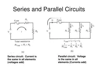
Section Simple Circuits 23.1 Current and Resistance in a Series Circuits • From the river model, you know that the sum of the drops in height is equal to the total drop from the top of the mountain to sea level. • In an electric circuit, the increase in voltage provided by the generator or other energy source, Vsource, is equal to the sum of voltage drops across lamps A and B, and is represented by the following equation: Vsource = VA + VB
Section Simple Circuits 23.1 Current and Resistance in a Series Circuits • To find the potential drop across a resistor, multiply the current in the circuit by the resistance of the individual resistor. • Because the current through the lamps is the same, VA = IRA and VB = IRB. • Therefore, VA = IRA + IRB, or Vsource = I(RA + R)B. • The current through the circuit is represented by the following equation:
Section Simple Circuits 23.1 Current and Resistance in a Series Circuits • The same idea can be extended to any number of resistances in series, not just two. • The same current would exist in the circuit with a singe resistor, R, that has a resistance equal to the sum of the resistances of the two lamps. Such a resistance is called the equivalent resistance of the circuit. • The equivalent resistance of resistors in series equals the sum of the individual resistances of the resistors.
Equivalent Resistance for Resistors in Series R = RA + RB + … Section Simple Circuits 23.1 Current and Resistance in a Series Circuits • For resistors in series, the equivalent resistance is the sum of all the individual resistances, as expressed by the following equation. • Notice that the equivalent resistance is greater than that of any individual resistor. • Therefore, if the battery voltage does not change, adding more devices in series always decreases the current.
Current Section Simple Circuits 23.1 Current and Resistance in a Series Circuits • To find the current through a series circuit, first calculate the equivalent resistance and then use the following equation. • Current in a series circuit is equal to the potential difference of the source divided by the equivalent resistance.
Section Simple Circuits 23.1 Voltage Drops in a Series Circuit • As current moves through any circuit, the net change in potential must be zero. • This is because the circuit’s electric energy source, the battery or generator, raises the potential an amount equal to the potential drop produced when the current passes through the resistors. • Therefore, the net change is zero.
Section Simple Circuits 23.1 Voltage Drops in a Series Circuit • An important application of series resistors is a circuit called a voltage divider. • A voltage divider is a series circuit used to produce a voltage source of desired magnitude from a higher-voltage battery. • For example, suppose you have a 9-V battery but need a 5-V potential source. • Consider the circuit shown in the figure.
Section Simple Circuits 23.1 Voltage Drops in a Series Circuit • Two resistors, RA and RB, are connected in series across a battery of magnitude V. • The equivalent resistance of the circuit is R = RA + RB. • The current is represented by the following equation:
Section Simple Circuits 23.1 Voltage Drops in a Series Circuit • The desired voltage, 5 V, is the voltage drop, VB, across resistor RB: VB = IRB. • Into this equation, the earlier equation for current is substituted.
Section Simple Circuits 23.1 Voltage Drops in a Series Circuit • Voltage dividers often are used with sensors, such as photoresistors. • The resistance of a photoresistor depends upon the amount of light that strikes it. • Photoresistors are made of semiconductors, such as silicon, selenium, or cadmium sulfide. • A typical photoresistor can have a resistance of 400 Ω when light is striking it compared with a resistance of 400,000 Ω when the photoresistor is in the dark.
Section Simple Circuits 23.1 Voltage Drops in a Series Circuit • The voltage output of a voltage divider that uses a photoresistor depends upon the amount of light striking the photoresistor sensor. • This circuit can be used as a light meter, such as the one shown in the figure.
Section Simple Circuits 23.1 Voltage Drops in a Series Circuit • In this device, an electronic circuit detects the potential difference and converts it to a measurement of illuminance that can be read on the digital display. The amplified voltmeter reading will drop as illuminance increases.
Section Simple Circuits 23.1 Voltage Drops in a Series Circuit Two resistors, 47.0 Ω and 82.0 Ω, are connected in series across a 45.0-V battery. • What is the current in the circuit? • What is the voltage drop across each resistor? • If the 47.0-Ω resistor is replaced by a 39.0-Ω resistor, will the current increase, decrease, or remain the same? • What is the new voltage drop across the 82.0-Ω resistor?
Section Simple Circuits 23.1 Voltage Drops in a Series Circuit Step 1: Analyze and Sketch the Problem
Section Simple Circuits 23.1 Voltage Drops in a Series Circuit Draw a schematic of the circuit.
Section Simple Circuits 23.1 Voltage Drops in a Series Circuit Identify the known and unknown variables. Known: Vsource = 45.0 V RA = 47.0 Ω RB = 82.0 Ω Unknown: I = ? VA = ? VB = ?
Section Simple Circuits 23.1 Voltage Drops in a Series Circuit Step 2: Solve for the Unknown
and R = RA + RB Section Simple Circuits 23.1 Voltage Drops in a Series Circuit • To determine the current, first find the equivalent resistance.
Section Simple Circuits 23.1 Voltage Drops in a Series Circuit Substitute R = RA + RB Substitute Vsource = 45.0 V, RA = 47.0 Ω,RB = 82.0 Ω = 0.349 A
Section Simple Circuits 23.1 Voltage Drops in a Series Circuit • Use V = IR for each resistor. VA = IRA Substitute I = 0.349 A, RA = 47.0 Ω VA= (0.349 A)(47.0 Ω) = 16.4 V
Section Simple Circuits 23.1 Voltage Drops in a Series Circuit VB = IRB Substitute I = 0.349 A, RA = 82.0 Ω VB = (0.349 A)(82.0 Ω) = 28.6 V
Section Simple Circuits 23.1 Voltage Drops in a Series Circuit • Calculate current, this time using 39.0 Ω as RA.
Section Simple Circuits 23.1 Voltage Drops in a Series Circuit Substitute Vsource = 45.0 V, RA = 39.0 Ω,RB = 82.0 Ω = 0.372 A The current will increase.
Section Simple Circuits 23.1 Voltage Drops in a Series Circuit • Determine the new voltage drop in RB. VB = IRB Substitute I = 0.372 A, RA = 82.0 Ω VB = (0.372 A)(82.0 Ω) = 30.5 V
Section Simple Circuits 23.1 Voltage Drops in a Series Circuit Step 3: Evaluate the Answer
Section Simple Circuits 23.1 Voltage Drops in a Series Circuit • Are the units correct? Current is A = V/Ω; voltage is V = A·Ω. • Is the magnitude realistic? For current, if R > V, I < 1. The voltage drop across any one resistor must be less than the voltage of the circuit. Both values of VB are less than Vsource, which is 45 V.
Section Simple Circuits 23.1 Voltage Drops in a Series Circuit • Step 1: Analyze and Sketch the Problem • Draw a schematic of the circuit. • Step 2: Solve for the Unknown • Step 3: Evaluate the Answer The steps covered were:
Section Simple Circuits 23.1 Parallel Circuits • Look at the circuit shown in the figure below. • How many current paths are there?
Section Simple Circuits 23.1 Parallel Circuits • The current from the generator can go through any of the three resistors. • A circuit in which there are several current paths is called a parallel circuit. • The three resistors are connected in parallel; both ends of the three paths are connected together. • In the mountain river model, such a circuit is illustrated by three paths for the water over a waterfall.
Section Simple Circuits 23.1 Parallel Circuits • Some paths might have a large flow of water, while others might have a small flow. • The sum of the flows, however, is equal to the total flow of water over the falls. • In addition, regardless of which channel the water flows through, the drop in height is the same. • Similarly, in a parallel electric circuit, the total current is the sum of the currents through each path, and the potential difference across each path is the same.
Section Simple Circuits 23.1 Series Circuits • What is the current through each resistor in a parallel electric circuit? • It depends upon the individual resistances. • For example, in the figure, the potential difference across each resistor is 120 V.
Section Simple Circuits 23.1 Series Circuits • The current through a resistor is given by I = V/R, so you can calculate the current through the 24-Ω resistor as I = (120 V)/(24 Ω) = 5.0 A and then calculate the currents through the other two resistors. • The total current through the generator is the sum of the currents through the three paths, in this case, 38 A.
Section Simple Circuits 23.1 Series Circuits • What would happen if the 6-Ω resistor were removed from the circuit? • Would the current through the 24-Ω resistor change? • The current depends only upon the potential difference across it and its resistance; because neither has changed, the current also is unchanged.
Section Simple Circuits 23.1 Parallel Circuits • The same is true for the current through the 9-Ω resistor. • The branches of a parallel circuit are independent of each other. • The total current through the generator, however, would change. • The sum of the currents in the branches would be 18 A if the 6-Ω resistor were removed.
Section Simple Circuits 23.1 Resistance in a Parallel Circuit • How can you find the equivalent resistance of a parallel circuit? • In the figure shown, the total current through the generator is 38 A.
Section Simple Circuits 23.1 Resistance in a Parallel Circuit • Thus, the value of a single resistor that results in a 38-A current when a 120-V potential difference is placed across it can easily be calculated by using the following equation: = 3.2 Ω