Download
1 / 18
180 likes | 264 Views
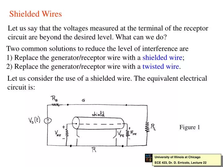
Shielded Wires. Let us say that the voltages measured at the terminal of the receptor circuit are beyond the desired level. What can we do?. Two common solutions to reduce the level of interference are 1) Replace the generator/receptor wire with a shielded wire ;

E N D
Shielded Wires Let ussay that the voltages measured at the terminal of the receptor circuit are beyond the desired level. What can we do? Two common solutions to reduce the level of interference are 1) Replace the generator/receptor wire with a shielded wire; 2) Replace the generator/receptor wire with a twisted wire. Let us consider the use of a shielded wire. The equivalent electrical circuit is: Figure 1 University of Illinois at Chicago ECE 423, Dr. D. Erricolo, Lecture 22
The reference conductor can be either another wire Figure 2 or a common ground plane Figure 3 University of Illinois at Chicago ECE 423, Dr. D. Erricolo, Lecture 22
In both cases the transmission line contains 4 conductors, hence the results previously found are not applicable. Solutions for a multi- conductor transmission line can be computed using programs that solve the corresponding equations, which are, in the frequency domain: (1) (2) where (3) Note that losses in the medium have been neglected University of Illinois at Chicago ECE 423, Dr. D. Erricolo, Lecture 22
We will not solve the multi-conductor transmission line equations here, but we will simply concentrate on the computations of the per-unit-length parameters. The equivalent circuit for a length dz of the transmission line, assuming TEM propagation mode, is: Figure 4 University of Illinois at Chicago ECE 423, Dr. D. Erricolo, Lecture 22
The per-unit length matrices are: (4) two elements are missing in the capacitance matrix! University of Illinois at Chicago ECE 423, Dr. D. Erricolo, Lecture 22
Referring to the following figure Figure 5 The mutual capacitances between 1) the generator and the receptor wires and 2) the receptor and reference wire are missing because of the presence of the shield. University of Illinois at Chicago ECE 423, Dr. D. Erricolo, Lecture 22
Computation of the per-unit length parameters Resistance Generator and receptor wires: and are computed in the usual manner Shield: its resistance depends on the construction technique. braided-wire shield (5) where resistance of one braid wire number of belts number of braid wires/belt weave angle solid shield (6) computed assuming well-developed skin-effect; shield interior radius shield thickness University of Illinois at Chicago ECE 423, Dr. D. Erricolo, Lecture 22
Inductance We will only consider computation of inductance parameters for the case of a ground plane reference conductor. (7) generator: (8) shield: receptor: (9) (10) generator-shield: The equality holds only if shield and generator wire are widely separated. Receptor-shield: (11) University of Illinois at Chicago ECE 423, Dr. D. Erricolo, Lecture 22
The fact that is very important since it explains how inductive coupling is eliminated. Consider the following circuit for the computation of the mutual inductance between shield and receptor: Figure 6 The mutual inductance may be computed by placing a current on the shield and determining the magnetic flux through the receptor circuit or, conversely, by placing a current on the receptor wire and determining the magnetic flux through the shield circuit. The second option is equivalent to placing all the current on the shield, which explains why University of Illinois at Chicago ECE 423, Dr. D. Erricolo, Lecture 22
Capacitance Per-unit length cpacitances are obtained using the relation (12) The medium inside the shield may have . The capacitance between the receptor wire and the shield is the same as for a coaxial cable: (13) The other capacitances may be obtained applying (12) to the subsystem constituted by the generator wire and the shield so that: (14) It can be shown that: (15) University of Illinois at Chicago ECE 423, Dr. D. Erricolo, Lecture 22
Capacitive coupling The notion of cross-talk voltages being composed of capacitive and inductive contributions holds for coupled, electrically short lines. Let us use some results for small frequency. Consider the following circuit: Figure 7 Capacitive coupling through and leads to: (16) University of Illinois at Chicago ECE 423, Dr. D. Erricolo, Lecture 22
When the frequency is sufficiently small, the cross-talk voltage may be approximated by: (17) where (18) is the low frequency value of the voltage along the generator wire. Observe that the form of (17) is equivalent to the one previously considered for the coupling between two wires without shield. In practice the shield is connected to the reference conductor at both ends, so that its voltage is reduced to zero and the capacitive coupling contribution is removed. When the line is not electrically short, one has to connect the shield to the reference conductor at many points spaced by an amount of to remove the capacitive coupling. University of Illinois at Chicago ECE 423, Dr. D. Erricolo, Lecture 22
Inductive coupling We have seen that shield must be grounded at both ends to remove capacitive coupling: the same must be done in order to remove inductive coupling. To understand this concept, let us consider the effect of the shield around the receptor wire. Figure 8 The current generates a magnetic flux that is picked up by the shield-reference circuit. By Faraday’s law, the resulting emf induces a current in the shield. The magnetic flux associated with tends to cancel . University of Illinois at Chicago ECE 423, Dr. D. Erricolo, Lecture 22
Let us consider in more detail the mechanism of inductive coupling. Our considerations will be based upon the following circuit for the shield receptor wire: Figure 9 From this circuit we easily obtain that: (19) where (20) University of Illinois at Chicago ECE 423, Dr. D. Erricolo, Lecture 22
Substitution of (20) into (19) yields: (21) Now we use the relations: (22) which give (23) (24) University of Illinois at Chicago ECE 423, Dr. D. Erricolo, Lecture 22
So the results previously found without shield are still valid provided that they are multiplied by the factor. (25) The shield factor is approximated by (26) so that, overall, the behavior of the inductive cross-talk contribution as a function of the frequency is: Figure 10 University of Illinois at Chicago ECE 423, Dr. D. Erricolo, Lecture 22
From a qualitative viewpoint there are two different situations: 1) : The lowest impedance path goes through the ground plane so the flux due to threads the entire receptor circuit. 2) : The lowest impedance path goes through the shield, instead of the ground plane, resulting in which causes no magnetic flux threading the receptor circuit. To summarize, when the shield is grounded at both ends the inductive coupling contributions are given by the following transfer functions. (27) (28) University of Illinois at Chicago ECE 423, Dr. D. Erricolo, Lecture 22
Effect of pigtails “Pigtails” refer to a break in a shield required to terminate it to a grounding point. The interior shielded wire is exposed to direct radiation from the pigtail section. As a result, the shielding effectiveness is reduced University of Illinois at Chicago ECE 423, Dr. D. Erricolo, Lecture 22