Download
1 / 39
400 likes | 538 Views
DETECTOR TECHNOLOGIES Lecture 4 : Radiation Detectors - Scintillation - Čerenkov - TRD. Scintillation : principles. Scintillator : a material which emits light (photons), when stimulated. Of course, we need a light sensor to transform the light in an electric signal.

E N D
DETECTOR TECHNOLOGIES Lecture 4 : Radiation Detectors - Scintillation - Čerenkov - TRD
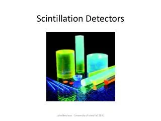
Scintillation : principles Scintillator: a materialwhichemits light (photons), whenstimulated Of course, weneed a light sensor to transform the light in an electric signal ≈ nsec. - µsec. Fluorescence ≈ µsec. - minsPhosphorescence Light intensity : Read out Photo detector Scintillator Ligth guide
Scintillation : principles For a scintillator, whatis important ? - Scintillation efficiency: energyneeded for 1 - emission - Light spectrum: in order to adapt the read out system to the proper wavelength - Light decay time - absorption - Transparency: the emitted should not bere-absorbed. 2 types of scintillators : Organics (liquids, plastics) Inorganics (crystals,liquids) Advantage : FastAdvantages : good efficiency Disadvantages : ratherinnefficients good linearity non-linear (needquenching) radiation tolerance not good for ‘s Disadvantages : relatively slow expensive (if crystals) Usedmainly for trigger purposeUsedmainly for measurements
Scintillation : Organicscintillators • Excitation of organicmolecules • Yield≈ 1 per loss of 100 eV • λ ≈100 nm (UV) • Absorption and re-emission • λ≈300 nm (UV) • Absorption and re-emission • λ≈ 400 nm (Blue) OrganicScintillators : Waveshifter (adapts to the read-out) slows the process induce a non-linearity Luminescence (Birk’slaw) per lenght S = emissionefficiency KB = Birk’s constant (exp.) Low Z (organic = Hydrogen + Carbon) lowefficiency for HE (only Compton effect) but good efficiency for neutrons
Scintillation : Organicscintillators Wavelenght shift
Scintillation : Inorganicscintillators : crystals Crystals (NaI, CsI, BGO, PbWO4…) Energylosswillinduceelectron-hole pairs creation migration to activation centers (fast) - excitation – transition - emission trapping (slow) Activatorischoosen for visible emission 2 or more wavelenghts (addition of activator) Liquid noble gases (Lar, Lxe, LKr) Still 2 time constants Samewavelengths (pure gases) Precisionmeasurements
Scintillation : Inorganicscintillators Inorganiccrystals are temperature-sensitive (calorimeters have to becooled)
Scintillation : Transport of light The readout has to be adapted to geometry and emission spectrum of the scintillator. Light guide Total reflection inside the light guide Material : PPMA (Polymethylmethacrylat) Plexiglas (C5O2H8)n
Scintillation : Transport of light Optical fiber Improved aperture with multi-cladding
Scintillation : Transport of light Scintillatingfiber : opticalfiberfilledwithscintillator (plastic or liquid) Stack of SciFibers (UA2)
Scintillation : Photodetector Photodetector : Convert the scintillatingligthinto usable electronic signal (HE Physics : usually visible and UV spectrum) = Convert UV and visible photons in electrons Requirement : High conversion efficiency QE = N photo-electrons / N photons
Scintillation : Photomultiplier Requirement : High conversion efficiency QE = N photo-electrons / N photons Total gain : Resolution : linearity statistics And … Sensitivity to magneticfield δ = N electronsproduced / N electronsincoming n = number of dynodes
Scintillation : Photomultipliersevolutions Multi anode PMT Resistant to magneticfield
Scintillation : HPD Hybrid Photo Diode (HPD) highlysegmentedread out Good sensitivity (PMT like) Speed Lesssensistive to Mag. Field Precision
Scintillation : HPD LHCb : Cerenkovsread-out with HPDS
Scintillation : HPD Cms /HCAL read-out withHPDs
Scintillation : APD Avalanche Photo Diode (APD) : an all-silicondevice. - high photo conversion Q eff≈ 0.7 - Very high electricfield 10 5 V/m(avalanche mode) - Thick - Linear mode Good tolerancewithmag. Field good (?) tolerance to radiation
Scintillation : APD CMS APDs : ≈ 141 500 Pieces for the ECAL (scintillator : PWBO4) Active size : 5 x 5 mm2
Scintillation : SiPM PPD : Pixelized Photon Detector = SiPM : SiliconPhotomultplicator = APDs in parallelwithresistors - high photo conversion Q eff≈ 0.7 - Very high Gain (10 5) - Geiger mode - Pixelized - Not a proportionalcounter - Very good position counter - Adapted to fibers (small surface)
Čerenkov Čerenkov Detectors Particle travelling fasterthan light in a given medium emits radiation (photons) and The emission of Čerenkov light depensdirectlyfrom the speed of the particle depensindirectlyfrom the mass of the particle The maximum angle depensonlyfrom the medium. Typical : 0.35 µm < λcerenkov< 0.55 µm (usual medium : 1 < n < 2)
Čerenkov Radiation intensity (Franck-Tamm formula) : α = 1 / 137 λ = Cerenkov light θ = Cerenkov angle For a charged (1) particle, = 1
ThresholdČerenkov ThresholdCrenekovdetectors make a simple decision on wether the particle isabove or below the Cerenkovthresholdvelocity. Used for differentiatingheavyparticles (π, K, p) Changing the thegas pressure Changes the refractive index
ThresholdČerenkov Aerogel : silicate gel (99.8% Air)
RICH Čerenkov Ring Imaging Cherenkov (Ypsilantis and Seguinot -1977)
RICH Čerenkov The LHCb RICH C 4 F 10 in RICH 1 (n = 1.0014) CF 4 in RICH 2 (n = 1.005) Read-out : HPDs
Transition Radiation Detector Transition radiationis a photon emission (X) occuringwhen a charged particle passes through inhomogeneous media, such as a boundary between two different media with different dielectric properties Emission at an angle Verylow rate
Transition Radiation Detector ALICE TRD
Transition Radiation Detector ALICE TRD
Transition Radiation Detector ATLAS TRT : CombinationTracker / TRD About 300 000 Straw tubes : position measurement by dE/dX radiation occurs on the wall of the tube
Transition Radiation Detector ATLAS TRT : CombinationTracker / TRD About 300 000 Straw tubes : position measurement by dE/dX radiation occurs on the wall of the tube