Download
1 / 18
180 likes | 280 Views
MAC Simulation Results and Methodology (60GHz). Date: 2013-11-12. Presenter:. Authors/Supporters List. Authors/Supporters List. Proposal overview. This presentation is part and in support of the complete proposal described in 802.11-13/1301r0 (slides) and 802.11-13/1302r0 (text) that:

E N D
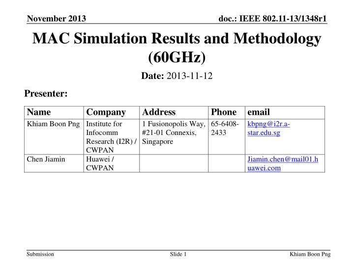
MAC Simulation Results and Methodology (60GHz) Date: 2013-11-12 Presenter: Khiam Boon Png
Authors/Supporters List Khiam Boon Png
Authors/Supporters List Khiam Boon Png
Proposal overview • This presentation is part and in support of the complete proposal described in 802.11-13/1301r0 (slides) and 802.11-13/1302r0 (text) that: • Enables the low power/low cost portable/mobile devices and the high performance devices, guaranteeing interoperability and communication between 802.11aj and 802.11ad devices • Supports dynamic bandwidth operation at 1.08GHz/2.16GHz channel • Supports dynamic channel transfer to coordinate the allocation of operating channel • Supports opportunistic transmissions and refined spatial sharing • Supports enhanced mobile device support mode • Supports distortion compensation for I/Q imbalance and PA nonlinearity Khiam Boon Png
Scope of this presentation As shown in this presentation, all TGaj performance requirements have been met and all needed performance results delivered Khiam Boon Png
FRD Section 2.1.1 Maximum Throughput(at least 1 Gbps at MAC SAP) (1/5) • Scenario 1a and 1c: one PBSS operating in 2.16 GHz large band is shown in the right • PCP/AP is located at (0, 0) • mSTA1 is located in (1.5, 0.5) • mSTA2 is located in (0.5, 1.5) • mSTA3 is located in (-1.5, -0.5) • mSTA4 is located in (-0.5, -1.5) • Parameters and assumptions are given as below: • Link 1: mSTA1 is the source with infinite buffer and has packets to send always; mSTA2 is the destination and all packets from mSTA1 are destined to mSTA2 • Link 2: mSTA3 is the source with infinite buffer and has packets to send always; mSTA4 is the destination and all packets from mSTA3 are destined to mSTA4 • All MPDU sizes are 8000 bytes, MAC header 40 bytes, and PHY header 32 bytes • Control PHY rate = 27.5 Mbps • OFMD PHY rate = 6,756.75 Mbps (MCS 24, 64-QAM) and LOS channel • Antenna Gain: Tx = 8 dB; Rx = 8 dB. mSTA2 mSTA1 PCP/AP mSTA3 mSTA4 Khiam Boon Png
FRD Section 2.1.1 Maximum Throughput(at least 1 Gbps at MAC SAP) (2/5) • Scenario 1b or 1d: two PBSSs operating in their own 1.08 GHz small bands under DBC MAC protocol (IEEE 802.11-13/1291r1) is shown in the right • PCP/AP 1 is located at (0.5,0.5) • mSTA1 is located in (1.5, 0.5) • mSTA2 is located in (0.5, 1.5) • PCP/AP 2 is located at (-0.5, -0.5) • mSTA3 is located in (-1.5, -0.5) • mSTA4 is located in (-0.5, -1.5) • Parameters as defined as below • Link 1 in PBSS 1:mSTA1 is the source with infinite buffer and has packets to send always; mSTA2 is the destination and all packets from mSTA1 are destined to mSTA2 • Link 2 in PBSS 2: mSTA3 is the source with infinite buffer and has packets to send always; mSTA4 is the destination and all packets from mSTA3 are destined to mSTA4 • All MPDU sizes are 8000 bytes, MAC header 40 bytes, and PHY header 32 bytes • Control PHY rate = 13.75 Mbps • OFDM PHY rate = 3,378.375 Mbps (MCS 24, 64-QAM) and LOS channel • Antenna Gain: Tx = 8 dB; Rx = 8 dB. mSTA2 mSTA1 PCP/AP1 PCP/AP2 mSTA3 mSTA4 Khiam Boon Png
FRD Section 2.1.1 Maximum Throughput(at least 1 Gbps at MAC SAP) (3/5) • Allocation of SPs under Scenario 1a • Allocation of SPs under Scenario 1b • Each STA is configured with one antenna containing 12 sectors. • Other parameters are defined in IEEE 802.11ad specification. • Immediate-ACK • Note that for Scenario 1b, SIFS is set to 3 µs (or 6 µs) and aSlotTime is set to 8 µs. 170 µs 170 µs 20 ms 17.308 ms 20 ms Khiam Boon Png
FRD Section 2.1.1 Maximum Throughput(at least 1 Gbps at MAC SAP) (4/5) • Allocation of CBAPs under Scenario 1c • Allocation of CBAPs under Scenario 1d • Each STA is configured with one antenna containing 12 sectors. • Other parameters are defined in IEEE 802.11ad specification. • RTS/CTS mechanism • Note that for Scenario 1b, SIFS is set to 3 µs (or 6 µs) and aSlotTime is set to 8 µs. 18.87ms 20 ms 17.308 ms 20 ms Khiam Boon Png
FRD Section 2.1.1 Maximum Throughput(at least 1 Gbps at MAC SAP) (5/5) • Simulation Results: Khiam Boon Png
FRD Section 2.1.2 Range Requirement(1 Gbps at 10 meters) (1/5) • Scenario 2a and 2c: one PBSS operating in 2.16 GHz large band is shown in the right • PCP/AP is located at (0, 0) • mSTA1 is located in (0, 5) • mSTA2 is located in (0, -5) • Parameters and assumptions are given as below: • Link 1: mSTA1 is the source with infinite buffer and has packets to send always; mSTA2 is the destination and all packets from mSTA1 are destined to mSTA2. • All MPDU sizes are 8000 bytes, MAC header 40 bytes, and PHY header 32 bytes • Control PHY rate = 27.5 Mbps • OFDM PHY rate = 2,079 Mbps (MCS 17, QPSK) and NLOS channel • Antenna Gain: Tx = 14 dB; Rx = 14 dB. mSTA1 PCP/AP mSTA2 Khiam Boon Png
FRD Section 2.1.2 Range Requirement(1 Gbps at 10 meters) (2/5) • Scenario 2b or 2d: two PBSSs operating in their own 1.08 GHz small bands under DBC MAC protocol (IEEE 802.11-13/1291r1) is shown in the right • PCP/AP 1 is located at (0,0.5) • mSTA1 is located in (0, 5) • mSTA2 is located in (0, -5) • PCP/AP 2 is located at (-0.5, 0) • mSTA3 is located in (-5, 0) • mSTA4 is located in (5, 0) • Parameters as defined as below • Link 1 in PBSS 1: mSTA1 is the source with infinite buffer and has packets to send always; mSTA2 is the destination and all packets from mSTA1 are destined to mSTA2. • Link 2 in PBSS 2: mSTA3 is the source with infinite buffer and has packets to send always; mSTA4 is the destination and all packets from mSTA3 are destined to mSTA4. • All MPDU sizes are 8000 bytes, MAC header 40 bytes, and PHY header 32 bytes • Control PHY rate = 13.75 Mbps • OFDM PHY rate = 1,386 Mbps (MCS 18, 16-QAM) and NLOS channel • Antenna Gain: Tx = 14 dB; Rx = 14 dB. mSTA1 PCP/AP 1 PCP/AP 2 mSTA3 mSTA4 mSTA2 Khiam Boon Png
FRD Section 2.1.2 Range Requirement(1 Gbps at 10 meters) (3/5) • Allocation of SPs under Scenario 2a • Allocation of SPs under Scenario 2b • Each STA is configured with one antenna containing 12 sectors. • Other parameters are defined in IEEE 802.11ad specification. • Immediate-ACK • Note that for Scenario 1b, SIFS is set to 3 µs (or 6 µs) and aSlotTime is set to 8 µs. 19.0 ms 20 ms 17.298 ms 20 ms Khiam Boon Png
FRD Section 2.1.2 Range Requirement(1 Gbps at 10 meters) (4/5) • Allocation of CBAPs under Scenario 2c • Allocation of CBAPs under Scenario 2d • Each STA is configured with one antenna containing 12 sectors. • Other parameters are defined in IEEE 802.11ad specification. • RTS/CTS mechanism • Note that for Scenario 1b, SIFS is set to 3 µs (or 6 µs) and aSlotTime is set to 8 µs. 19.0 ms 20 ms 17.298 ms 20 ms Khiam Boon Png
FRD Section 2.1.2 Range Requirement(1 Gbps at 10 meters) (5/5) • Simulation Results: Khiam Boon Png
FRD Section 2.1.3 Video Requirement(3 Gbps at Home Living Room) (1/3) • Home living room scenario as defined in doc.: IEEE 802.11-12/1382r2 • Parameters and assumptions are given as below: • STB (PCP/AP): The source with infinite buffer and has packets to send always. • TV (STA): The destination and all packets from STB are destined to TV. • The PBSS operates in 2.16 GHz large band. • All MPDU sizes are 8000 bytes and all A-MPDU sizes are 256000 bytes. • MAC header 40 bytes, and PHY header 32 bytes. • Control PHY rate = 27.5 Mbps. • OFDM PHY rate = 4,504.5 Mbps (MCS 21, 16-QAM) and NLOS channel. • Antenna Gain: Tx = 14 dB; Rx = 14 dB. • Each STA is configured with one antenna containing 12 sectors. • Other parameters are defined in IEEE 802.11ad specification Khiam Boon Png
FRD Section 2.1.3 Video Requirement(3 Gbps at Home Living Room) (2/3) • Allocation of SPs under Scenario 3a and 3b • Allocation of SPs under Scenario 3c 2970 µs 210 µs 20 ms 4660 µs 120 µs 20 ms Khiam Boon Png
FRD Section 2.1.3 Video Requirement(3 Gbps at Home Living Room) (3/3) • Simulation Results: Khiam Boon Png


![Election Expenditure Monitoring [EEM] Assembly Elections- 2013](https://cdn1.slideserve.com/3400245/slide1-dt.jpg)