Download

1 / 96
1.1k likes | 1.4k Views
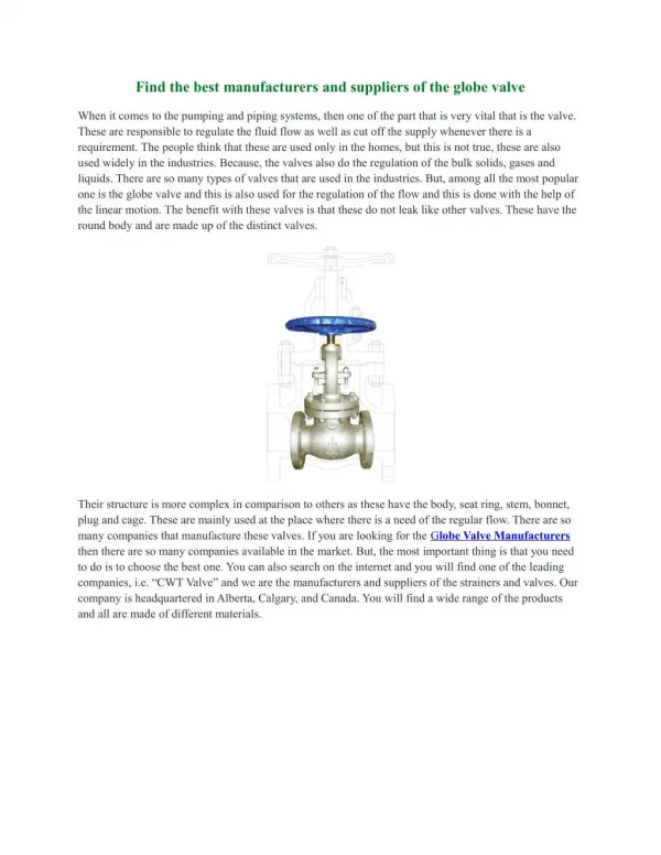
ANALYSIS OF PROCESSES OF MANUFACTURING OF GLOBE VALVE. BY WADHONKAR PAVANKUMAR D. BABHALE NIKHIL C. ASWAR RAVINDRA D. RACHATTE GIRISH M. Valve Body. LOCKING RING. SPRING WASHER. VALVE PLUG. SEAT RING. GUIDE BUSH. GLAND BUSH. PACKING SPREADOR - LOWER. PLUG PIN. PACKING SPREADOR UPPER.

E N D
ANALYSIS OF PROCESSES OF MANUFACTURING OF GLOBE VALVE BY WADHONKAR PAVANKUMAR D. BABHALE NIKHIL C. ASWAR RAVINDRA D. RACHATTE GIRISH M.
LOCKING RING SPRING WASHER
GUIDE BUSH GLAND BUSH
PACKING SPREADOR - LOWER PLUG PIN
PACKING SPREADOR UPPER VALVE STEM
Assignment 1 Study of ball valve
Introduction • A ball valve is a valve that opens by turning a handle attached to a ball inside the valve • The ball in the ball valve has a hole or port, through the middle • When the valve is closed, the hole is perpendicular to the ends of the valve
Importance and applications • Durable and usually work to achieve perfect shutoff • They are easy to repair operate, manually or by actuators • From the point of view of sealing, the concept of ball valve is the excellent.
Ball valve parts • A multitude of ball valve types and designs safely accommodate a wide variety of industrial applications. Regarding of type, all ball valves have the following basic parts- • Body • Bonnet • Trim • Ball and Seat • Stem and Sleeves • Actuator • Packing
Assignment 2 Study of three different types of trims
What is Trim ? • The internal elements of a valve are collectively referred to as a valve's trim. • The trim typically includes a disk, seat, stem & sleeves needed to guide the stem. • A valve's performance is determined by the disk and seat interface and the relation of the disk position to the seat. • Because of the trim, basic motions and flow control are possible.
Introduction • Aim : To calculate trim exit flow area and kinetic energy density at the outlet • To avoid the noise, erosion, cavitation, vibration in the valve • Therefore velocity must be reduced.
Introduction • What is flow coefficient ? The flow coefficient of a device is a relative measure of its efficiency at allowing fluid flow. • What is resistance coefficient of the valve ? A dimensionless number used in the study of flow resistance, equal to the resistance force in flow divided by one-half the product of fluid density, the square of fluid velocity, and the square of a characteristic length.
Cage trim with venturi shaped slots • Calculation of coefficient of resistance • Overall resistance coefficient
Concentric cage trim with offset drilled holes • Calculation of intersection area
Trim with expanding right angle turns • Introduction to trim with right angle expanding turns • Calculation of resistance coefficient • Value of resistance coefficient is more comparing to the other two methods
Conclusion • Venturi valve trim is not compatible for higher pressure drops • Concentric cage trim requires more space to get more pressure drop • Compatible for low space and more pressure drop
Project 2 Resistance coefficient for 16 cage trim
Introduction Aim : To calculate the coefficient of resistance, to calculate trim exit area and trim exit velocity Type of trim used concentric cage trim with offset drilled holes with 16 cages Significance : calculation of pressure drop in the trim
Calculation procedure Values for area are taken proportionally with respect to given input from example The formula to calculate the resistance coefficient is modified
Calculation (Continued) Calculation of resistance coefficient Value of resistance coefficient calculated from our calculation is 104.22 Outlet flow area Calculated value for outlet flow area is 6.72 (in * in)
Calculation (Continued) Trim exit velocity is Calculated value for trim exit velocity is 94.63 ft/sec
Conclusion Exit flow velocity is allowable (less than 100 ft/s) Trim can not fit into the valve
Calculation for 5 cages Calculation of resistance coefficient with same procedure ( Ko = 9.5) Trim exit velocity was not in the safe range (Vo = 313.18 ft/s) Both cases are not recommended
DESIGN OF TRIM WITH 10 EXPANDING RIGHT ANGLE TURNS Tortuous flow disc is type of trim which is used for controlling velocity and reducing pressure across the valve
CASE I • Cross section is ( 5 X 3) and ( 6 X 3) alternately • Value of resistance coefficient (Ko) = 121.99 • Outlet flow area (ao) = 7.2685 in2 • Exit flow velocity (VO) calculation = 99.33 ft/s • Disc diameters (ID X OD) = (50φ X 140φ) • Outlet flow area for 14 discs = 7.03 in2 Hence, outlet flow area for 14 discs is approximately equal with the calculation of outlet flow area from ‘Ko’. So, it is safe.
CASE II • Cross section at inlet is ( 5 X 3) and increasing to ( 5.1 X 3) • Value of resistance coefficient (Ko) = 121.99 • Outlet flow area (ao) = 7.2685 in2 • Exit flow velocity (VO) = 99.33 ft/s • Disc diameters (ID X OD) = (50φ X 150φ) • Outlet flow area for 15 discs = 6.2 in2 Hence, outlet flow area for 15 discs is not equal with the calculation of outlet flow area from ‘Ko’. So it is not recommended.
CASE III • Cross section at inlet is ( 5 X 3) and increasing to ( 5.2 X 3) • Value of resistance coefficient (Ko) = 121.99 • Outlet flow area (ao) = 7.2685 in2 • Exit flow velocity (VO) = 99.33 ft/s
SUMMERY OF CASE III • Disc diameters (ID X OD) = (50φ X 153φ) Outlet flow area for 15 discs = 6.3 in2 • Disc diameters (50φ X 160φ) Outlet flow area for 12 discs = 7.03 in2 • Disc diameters (50φ X 155φ) Outlet flow area for 15 discs = 6.29 in2 • Disc diameters (50φ X 163φ) Outlet flow area for 15 discs = 7.55 in2 • Disc diameters (65φ X 178φ) Outlet flow area for 10 discs = 7.16 in2
CALCULATION OF PRESURRE DROP CASE I • Considering rectangular cross section • P2 – P1 = [ + hL] hL = • Pressure drop = 159.36 psi • Pressure drop for 10 turns = 10 X 159.36 = 1593.6 psi • We required pressure drop of 1820 psi in 10 turns and calculated is 1593.6 psi.
CASE II • In this case input flow rate value is changed. • Pressure drop = 140 psi • Pressure drop for 10 turns = 10 X 140 = 1400 psi • We required pressure drop of 1820 psi in 10 turns and calculated is 1400 psi.
CASE III • To calculate pressure drop for second right angle turn • Section 3 – (5.2 X 3) • Here, width – 5.2 mm and depth – 3 mm • Section 6 – (6.24 X 3) • Pressure drop = 114.84 psi
CASE IV • With the same cross sections as case III Keep velocity less than 30 m/s in the trim • Pressure drop = 46.4 psi • Pressure drop for 10 turns = 10 X 46.4 = 464 psi • We required pressure drop of 1820 psi in 10 turns and calculated is 464 psi.
conclusion • Any case is not recommended as pressure drop required is less than required. • This type of trim design can be used for valves requiring less pressure drops.
DESIGN OF 5 CAGE TRIM WITH GAP BETWEEN TWO CAGES AND PRESSURE DROP CALCULATION Project 4
Introduction • Aim of the project : Design the five cage trim to get the pressure drop of 700 psi at the outlet of trim • Significance : 1) To reduce the noise 2) To avoid wear and tear of the valve 3) To avoid the vibration • Use of the baffle plate
Design Aspects • The velocity through the one hole of the cage should be maximum 30 m/s • Pressure drop decides the no. of cages and there is a limit for maximum no of cages. • Direction of the flow should be decided
Sequence of Calculation • Calculate velocity in the valve • Calculate diameters of cages • Calculate diameter of one hole in the cage • Calculate area of the gap between the cages & velocity at that section • Calculate pressure drop in every cage of trim & Hence pressure drop across the trim • Calculate pressure drop across the baffle plate connected • Calculate total pressure drop across the valve
Input data • Flow rate (Q) = 265000 l/hr • Density of liquid (ρ) = 720 to 860 kg/m3 • Valve size = 4” 900 class • Required pressure drop – calculate maximum achievable pressure drop
Calculation Procedure • Inlet velocity v1 = Q/A1 • Diameter of the cages • Calculation of diameter of one hole in the cage • Total area provided in cage 1 = Q/v • Internal circumference of cage 1 • No of holes per cage = Internal circumference of cage pitch • Total no of holes in one cage = No of holes per cage * No. of rows • Area of one hole in first cage = Total area provided in cage 1 Total no of holes in one cage
Calculation Procedure • Pressure drop calculation: 1) head loss due to friction = k vo2/ (2*gn) 2) ΔP = ρ* gn [(z1-z2) + (vo2- vi2)/ (2*gn) + hL] • Velocity in the gap: 1) Area of gap between two cages 2) Flow through gap = total flow no. Of holes in the cage 1 3) Velocity in the gap = flow through gap area of gap