Download
1 / 35
360 likes | 541 Views
ECE 448 Lecture 4. Simple Testbenches. Testbench Defined. Testbench = VHDL entity that applies stimuli (drives the inputs) to the Design Under Test (DUT) and (optionally) verifies expected outputs. The results can be viewed in a waveform window or written to a file.

E N D
ECE 448 Lecture 4 Simple Testbenches ECE 448 – FPGA and ASIC Design with VHDL
Testbench Defined • Testbench= VHDL entity that applies stimuli (drives the inputs) to the Design Under Test (DUT) and (optionally) verifies expected outputs. • The results can be viewed in a waveform window or written to a file. • Since Testbench is written in VHDL, it is not restricted to a single simulation tool (portability). • The same Testbench can be easily adapted to test different implementations (i.e. different architectures) of the same design. ECE 448 – FPGA and ASIC Design with VHDL
Testbench Processes Generating Stimuli Design Under Test (DUT) Observed Outputs ECE 448 – FPGA and ASIC Design with VHDL
Possible sources of expected results used for comparison Testbench actual results VHDL Design = ? Representative Inputs Manual Calculations or Reference Software Implementation(C, Java, Matlab ) expected results ECE 448 – FPGA and ASIC Design with VHDL
Testbench The same testbench can be used to test multiple implementations of the same circuit (multiple architectures) testbench design entity . . . . Architecture N Architecture 2 Architecture 1 ECE 448 – FPGA and ASIC Design with VHDL
Testbench Anatomy ENTITYmy_entity_tbIS --TB entity has no ports ENDmy_entity_tb; ARCHITECTUREbehavioralOFtbIS --Local signals and constants COMPONENT TestComp --All Design Under Test component declarations PORT ( ); END COMPONENT; ----------------------------------------------------- BEGIN DUT:TestComp PORT MAP( -- Instantiations of DUTs ); testSequence: PROCESS -- Input stimuli END PROCESS; ENDbehavioral; ECE 448 – FPGA and ASIC Design with VHDL
Testbench for XOR3 (1) LIBRARYieee; USEieee.std_logic_1164.all; ENTITY xor3_tbIS ENDxor3_tb; ARCHITECTUREbehavioralOFxor3_tbIS -- Component declaration of the tested unit COMPONENTxor3 PORT( A : IN STD_LOGIC; B : IN STD_LOGIC; C : IN STD_LOGIC; Result : OUT STD_LOGIC ); END COMPONENT; -- Stimulus signals - signals mapped to the input and inout ports of tested entity SIGNALtest_vector:STD_LOGIC_VECTOR(2 DOWNTO 0); SIGNAL test_result : STD_LOGIC; ECE 448 – FPGA and ASIC Design with VHDL
Testbench for XOR3 (2) BEGIN UUT : xor3 PORT MAP ( A => test_vector(2), B => test_vector(1), C => test_vector(0), Result => test_result); ); Testing: PROCESS BEGIN test_vector<="000"; WAIT FOR 10 ns; test_vector<="001"; WAIT FOR 10 ns; test_vector<="010"; WAIT FOR 10 ns; test_vector<="011"; WAIT FOR 10 ns; test_vector<="100"; WAIT FOR 10 ns; test_vector<="101"; WAIT FOR 10 ns; test_vector<="110"; WAIT FOR 10 ns; test_vector<="111"; WAIT FOR 10 ns; END PROCESS; ENDbehavioral; ECE 448 – FPGA and ASIC Design with VHDL
VHDL Design Styles dataflow VHDL Design Styles structural behavioral Concurrent statements Components and interconnects Sequential statements • Testbenches ECE 448 – FPGA and ASIC Design with VHDL
What is a PROCESS? • A process is a sequence of instructions referred to as sequential statements. The keyword PROCESS • A process can be given a unique name using an optional LABEL • This is followed by the keyword PROCESS • The keyword BEGIN is used to indicate the start of the process • All statements within the process are executed SEQUENTIALLY. Hence, order of statements is important. • A process must end with the keywords END PROCESS. Testing: PROCESS BEGIN test_vector<=“00”; WAIT FOR 10 ns; test_vector<=“01”; WAIT FOR 10 ns; test_vector<=“10”; WAIT FOR 10 ns; test_vector<=“11”; WAIT FOR 10 ns; END PROCESS; ECE 448 – FPGA and ASIC Design with VHDL
The execution of statements continues sequentially till the last statement in the process. After execution of the last statement, the control is again passed to the beginning of the process. Testing: PROCESS BEGIN test_vector<=“00”; WAIT FOR 10 ns; test_vector<=“01”; WAIT FOR 10 ns; test_vector<=“10”; WAIT FOR 10 ns; test_vector<=“11”; WAIT FOR 10 ns; END PROCESS; Execution of statements in a PROCESS Order of execution Program control is passed to the first statement after BEGIN ECE 448 – FPGA and ASIC Design with VHDL
The last statement in the PROCESS is a WAIT instead of WAIT FOR 10 ns. This will cause the PROCESS to suspend indefinitely when the WAIT statement is executed. This form of WAIT can be used in a process included in a testbench when all possible combinations of inputs have been tested or a non-periodical signal has to be generated. Testing: PROCESS BEGIN test_vector<=“00”; WAIT FOR 10 ns; test_vector<=“01”; WAIT FOR 10 ns; test_vector<=“10”; WAIT FOR 10 ns; test_vector<=“11”; WAIT; END PROCESS; PROCESS with a WAIT Statement Order of execution Program execution stops here ECE 448 – FPGA and ASIC Design with VHDL
WAIT FOR vs. WAIT 0 0 1 1 2 2 3 3 WAIT FOR: waveform will keep repeating itself forever … WAIT: waveform will keep its state after the last wait instruction. … ECE 448 – FPGA and ASIC Design with VHDL
Specifying time in VHDL ECE 448 – FPGA and ASIC Design with VHDL
Time values (physical literals) - Examples 7 ns 1 min min 10.65 us 10.65 fs Numeric value Space Unit of time (dimension) ECE 448 – FPGA and ASIC Design with VHDL
Units of time Unit Definition Base Unit fs femtoseconds (10-15 seconds) Derived Units ps picoseconds (10-12 seconds) ns nanoseconds (10-9 seconds) us microseconds (10-6 seconds) ms miliseconds (10-3 seconds) sec seconds min minutes (60 seconds) hr hours (3600 seconds) ECE 448 – FPGA and ASIC Design with VHDL
Simple Testbenches ECE 448 – FPGA and ASIC Design with VHDL
Generating selected values of one input • SIGNAL test_vector : STD_LOGIC_VECTOR(2 downto 0); • BEGIN • ....... • testing: PROCESS • BEGIN • test_vector <= "000"; • WAIT FOR 10 ns; • test_vector <= "001"; • WAIT FOR 10 ns; • test_vector <= "010"; • WAIT FOR 10 ns; • test_vector <= "011"; • WAIT FOR 10 ns; • test_vector <= "100"; • WAIT FOR 10 ns; • END PROCESS; • ........ • END behavioral; ECE 448 – FPGA and ASIC Design with VHDL
Generating all values of one input SIGNAL test_vector : STD_LOGIC_VECTOR(3 downto 0):="0000"; BEGIN ....... testing: PROCESS BEGIN WAIT FOR 10 ns; test_vector <= test_vector + 1; end process TESTING; ........ END behavioral; ECE 448 – FPGA and ASIC Design with VHDL
Arithmetic Operators in VHDL (1) To use basic arithmetic operations involving std_logic_vectors you need to include the following library packages: LIBRARY ieee; USE ieee.std_logic_1164.all; USE ieee.std_logic_unsigned.all; or USE ieee.std_logic_signed.all; ECE 448 – FPGA and ASIC Design with VHDL
Arithmetic Operators in VHDL (2) You can use standard +, - operators to perform addition and subtraction: signal A : STD_LOGIC_VECTOR(3 downto 0); signal B : STD_LOGIC_VECTOR(3 downto 0); signal C : STD_LOGIC_VECTOR(3 downto 0); …… C <= A + B; ECE 448 – FPGA and ASIC Design with VHDL
Different ways of performing the same operation signal count: std_logic_vector(7 downto 0); You can use: count <= count + “00000001”; or count <= count + 1; or count <= count + ‘1’; ECE 448 – FPGA and ASIC Design with VHDL
Different declarations for the same operator Declarations in the package ieee.std_logic_unsigned: function “+” ( L: std_logic_vector; R:std_logic_vector) return std_logic_vector; function “+” ( L: std_logic_vector; R: integer) return std_logic_vector; function “+” ( L: std_logic_vector; R:std_logic) return std_logic_vector; ECE 448 – FPGA and ASIC Design with VHDL
Operator overloading • Operator overloading allows different argument types for a given operation (function) • The VHDL tools resolve which of these functions to select based on the types of the inputs • This selection is transparent to the user as long as the function has been defined for the given argument types. ECE 448 – FPGA and ASIC Design with VHDL
Generating all possible values of two inputs • SIGNAL test_ab : STD_LOGIC_VECTOR(1 downto 0); • SIGNAL test_sel : STD_LOGIC_VECTOR(1 downto 0); • BEGIN • ....... • double_loop: PROCESS • BEGIN • test_ab <="00"; • test_sel <="00"; • for I in 0 to 3 loop • for J in 0 to 3 loop • wait for 10 ns; • test_ab <= test_ab + 1; • end loop; • test_sel <= test_sel + 1; • end loop; • END PROCESS; • ........ • END behavioral; ECE 448 – FPGA and ASIC Design with VHDL
Generating periodical signals, such as clocks CONSTANT clk1_period : TIME := 20 ns; CONSTANT clk2_period : TIME := 200 ns; SIGNAL clk1 : STD_LOGIC; SIGNAL clk2 : STD_LOGIC := ‘0’; BEGIN ....... clk1_generator: PROCESS clk1 <= ‘0’; WAIT FOR clk1_period/2; clk1 <= ‘1’; WAIT FOR clk1_period/2; END PROCESS; clk2 <= not clk2after clk2_period/2; ....... END behavioral; ECE 448 – FPGA and ASIC Design with VHDL
Generating one-time signals, such as resets CONSTANT reset1_width : TIME := 100 ns; CONSTANT reset2_width : TIME := 150 ns; SIGNAL reset1 : STD_LOGIC; SIGNAL reset2 : STD_LOGIC := ‘1’; BEGIN ....... reset1_generator: PROCESS reset1 <= ‘1’; WAIT FOR reset_width; reset1 <= ‘0’; WAIT; END PROCESS; reset2_generator: PROCESS WAIT FOR reset_width; reset2 <= ‘0’; WAIT; END PROCESS; ....... END behavioral; ECE 448 – FPGA and ASIC Design with VHDL
Typical error SIGNAL test_vector : STD_LOGIC_VECTOR(2 downto 0); SIGNAL reset : STD_LOGIC; BEGIN ....... generator1: PROCESS reset <= ‘1’; WAIT FOR 100 ns reset <= ‘0’; test_vector <="000"; WAIT; END PROCESS; generator2: PROCESS WAIT FOR 200 ns test_vector <="001"; WAIT FOR 600 ns test_vector <="011"; END PROCESS; ....... END behavioral; ECE 448 – FPGA and ASIC Design with VHDL
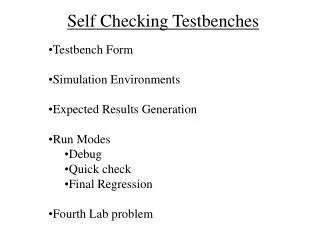
Asserts & Reports ECE 448 – FPGA and ASIC Design with VHDL
Assert Assert is a non-synthesizable statement whose purpose is to write out messages on the screen when problems are found during simulation. Depending on the severity of the problem, The simulator is instructed to continue simulation or halt. ECE 448 – FPGA and ASIC Design with VHDL
Assert - syntax ASSERT condition [REPORT "message" [SEVERITY severity_level ]; The message is written when the condition is FALSE. Severity_level can be: Note, Warning, Error (default), or Failure. ECE 448 – FPGA and ASIC Design with VHDL
Assert - Examples assert initial_value <= max_value report "initial value too large" severity error; assert packet_length /= 0 report "empty network packet received" severity warning; assert false report "Initialization complete" severity note; ECE 448 – FPGA and ASIC Design with VHDL
Report - syntax REPORT "message" [SEVERITY severity_level ]; The message is always written. Severity_level can be: Note (default), Warning, Error, or Failure. ECE 448 – FPGA and ASIC Design with VHDL
Report - Examples report "Initialization complete"; report "Current time = "& time'image(now); report "Incorrect branch" severity error; ECE 448 – FPGA and ASIC Design with VHDL
library IEEE; use IEEE.STD_LOGIC_1164.all; entity example_1_tb is end example_1_tb; architecture behavioral of example_1_tb is signal clk : std_logic := '0'; begin clk <= not clk after 100 ns; process begin wait for 1000 ns; report "Initialization complete"; report "Current time = " & time'image(now); wait for 1000 ns; report "SIMULATION COMPLETED" severity failure; end process; end behavioral; Simulation will stop automatically here ECE 448 – FPGA and ASIC Design with VHDL