Download
1 / 1
10 likes | 182 Views
Electromagnetic Compatibility (EMC)/Signal Integrity Members : Aaron Cook, Yatharth Khullar, Xi Wang, Ruofei Chen, Yugang Jing, Pak For Chu ; Team Advisors : Prof. J. V. Krogmeier, Prof. Barrett Robinson; Graduate mentors : Alex Layton, Andrew Balmos.

E N D
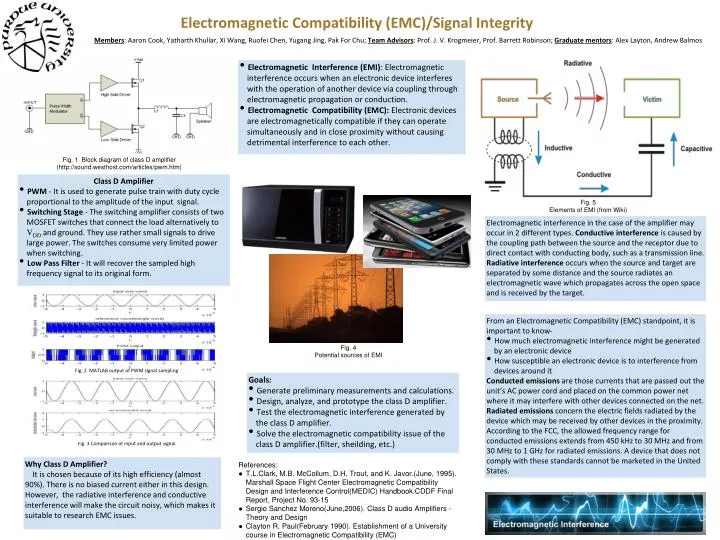
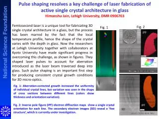
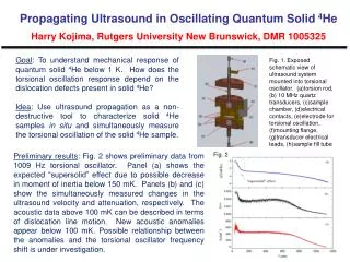
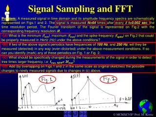
Electromagnetic Compatibility (EMC)/Signal Integrity Members: Aaron Cook, Yatharth Khullar, Xi Wang, Ruofei Chen, Yugang Jing, Pak For Chu; Team Advisors: Prof. J. V. Krogmeier, Prof. Barrett Robinson; Graduate mentors: Alex Layton, Andrew Balmos • Electromagnetic Interference (EMI): Electromagnetic interference occurs when an electronic device interferes with the operation of another device via coupling through electromagnetic propagation or conduction. • Electromagnetic Compatibility (EMC): Electronic devices are electromagnetically compatible if they can operate simultaneously and in close proximity without causing detrimental interference to each other. Fig. 1 Block diagram of class D amplifier (http://sound.westhost.com/articles/pwm.htm) Class D Amplifier • PWM - It is used to generate pulse train with duty cycle proportional to the amplitude of the input signal. • Switching Stage - The switching amplifier consists of two MOSFET switches that connect the load alternatively to VDD and ground. They use rather small signals to drive large power. The switches consume very limited power when switching. • Low Pass Filter - It will recover the sampled high frequency signal to its original form. Fig. 5 Elements of EMI (from Wiki) Electromagnetic interference in the case of the amplifier may occur in 2 different types. Conductive interference is caused by the coupling path between the source and the receptor due to direct contact with conducting body, such as a transmission line. Radiative interference occurs when the source and target are separated by some distance and the source radiates an electromagnetic wave which propagates across the open space and is received by the target. From an Electromagnetic Compatibility (EMC) standpoint, it is important to know- • How much electromagnetic interference might be generated by an electronic device • How susceptible an electronic device is to interference from devices around it Conducted emissions are those currents that are passed out the unit’s AC power cord and placed on the common power net where it may interfere with other devices connected on the net. Radiated emissions concern the electric fields radiated by the device which may be received by other devices in the proximity. According to the FCC, the allowed frequency range for conducted emissions extends from 450 kHz to 30 MHz and from 30 MHz to 1 GHz for radiated emissions. A device that does not comply with these standards cannot be marketed in the United States. Fig. 4 Potential sources of EMI Fig. 2 MATLAB output of PWM signal sampling Goals: • Generate preliminary measurements and calculations. • Design, analyze, and prototype the class D amplifier. • Test the electromagnetic interference generated by the class D amplifier. • Solve the electromagnetic compatibility issue of the class D amplifier.(filter, sheilding, etc.) Fig. 3 Comparison of input and output signal Why Class D Amplifier? It is chosen because of its high efficiency (almost 90%). There is no biased current either in this design. However, the radiative interference and conductive interference will make the circuit noisy, which makes it suitable to research EMC issues. References: • T.L.Clark, M.B. McCollum, D.H. Trout, and K. Javor.(June, 1995). Marshall Space Flight Center Electromagnetic Compatibility Design and Interference Control(MEDIC) Handbook.CDDF Final Report, Project No. 93-15 • Sergio Sanchez Moreno(June,2006). Class D audio Amplifiers - Theory and Design • Clayton R. Paul(February 1990). Establishment of a University course in Electromagnetic Compatibility (EMC)


![[I213 Discrete Signal Processing] MATLAB](https://cdn3.slideserve.com/6703415/slide1-dt.jpg)