Download
1 / 6
60 likes | 247 Views
Configuration Control. This sounds boring and what is this topic doing in the middle of a design reliability seminar?. Configuration Control Use of a “Standard” I/F Module. Design team comprised of members from multiple organizations

E N D
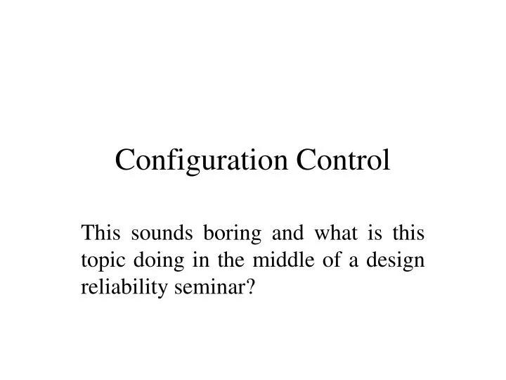
Configuration Control This sounds boring and what is this topic doing in the middle of a design reliability seminar?
Configuration ControlUse of a “Standard” I/F Module • Design team comprised of members from multiple organizations • “Standard” module (Shift Register) intended to be used throughout the system. • Four different versions found in 11 FPGAs. • Two use “reverse buffering” for the clocks • Two use clock trees. This programs design rules dictated that “reverse buffering” of clocks were to be used to control skew. Although that method can not guarantee performance, the rules were repeatedly violated.
“Reverse Buffering” Data Direction Clock Direction
Subsystem FPGA Version Used Clock Buffer Tree Used? A A1 1 Yes B B1 2 B2 2 B3 3 C C1 2 C2 2 D D1 2 D2 2 E E1 2 E2 1 Yes E3 4 Yes Configuration ControlDetails on “Standard” Structure Usage.
Configuration ControlSample Schematic Violation of the Projects "reverse buffering" clock topology.
Configuration ControlSample Schematic - Further Detail Sources of skew include routing between elements as well as the buffers in the tree. For Act 1 and Act 2 devices, routing and buffer delays can not be separated. Other considerations include rise time of the signal and the receivers threshold.