Download
1 / 36
360 likes | 429 Views
Rapid Prototyping using a Microprocessor Core on a Spartan II FPGA. Richard E. Haskell and Darrin M. Hanna CSE Dept., Oakland University, Rochester, MI 48309 Proc. Int. Conf. on Embedded Systems and Applications ESA’03, pp. 49-55 Las Vegas, Nevada, June 23-26, 2003.

E N D
Rapid Prototyping using a Microprocessor Coreon a Spartan II FPGA Richard E. Haskell and Darrin M. Hanna CSE Dept., Oakland University, Rochester, MI 48309 Proc. Int. Conf. on Embedded Systems and Applications ESA’03, pp. 49-55 Las Vegas, Nevada, June 23-26, 2003
Rapid Prototyping using a Microprocessor Coreon a Spartan II FPGA • A Digilent Prototyping Board • Xilinx Spartan IIE FPGA • The FC16 Forth Core • Rapid Prototyping of the DIO2 Peripheral Board • DIO2 buttons, LEDs, and 7-seg displays • Multiplication and Division • The Liquid Crystal Display • A Simple Decimal Calculator • Summary
Digilab 2E – Spartan IIE www.digilentinc.com
16x2 character LCD • Four seven segment displays • 16 LEDs in three colors • 8 switches • 15 pushbutton keypad • 8-bit VGAport • PS/2 port Digilab IO2 Board
cs oe we addr(5:0) data(7:0) 1 1 0 xxxx00 btns(7:0) 1 1 0 xxxx01 ‘0’&btns(14:8) 1 1 0 xxxx1x switchs 1 0 000100 leds(7:0) 1 0 000101 leds(15:8) 1 0 000110 sseg_reg(7:0) 1 0 000111 sseg_reg(15:8) Accessing the DIO2 Peripheral Board
The FC16 Forth Core
Hex Opcode Name Function Data Stack Instructions 0000 NOP No operation 0001 DUP Duplicate T and push data stack. N <= T; N2 <= N; 0002 SWAP Exchange T and N. T <= N; N <= T; 0003 DROP Drop T and pop data stack. T <= N; N <= N2; 0004 OVER Duplicate N into T and push data stack. T <= N; N <= T; N2 <= N; 0005 ROT Rotate top 3 elements on stack clockwise. T <= N2; N <= T; N2 <= N; 0006 -ROT Rotate top 3 elements on stack counter-clockwise. T <= N; N <= N2; N2 <= T; 0007 NIP Drop N and pop rest of data stack. T is unchanged. N <= N2; 0008 TUCK Duplicate T into N2 and push rest of data stack. N2 <= T; 0009 ROT_DROP Drop N2 and pop rest of data stack. T and N are unchanged. Equivalent to ROT DROP 000A ROT_DROP_SWAP Drop N2 and pop rest of data stack. T and N are exchanged. Equivalent to ROT DROP SWAP
The FC16 Forth Core
Hex Opcode Name Function Funit16 Instructions (fcode = lower 6 bits of opcode) 0010 + Pop N and add it to T. 0011 - Pop T and subtract it from N. 0012 1+ Add 1 to T 0013 1- Subtract 1 from T 0014 INVERT Complement all bits of T. 0015 AND Pop N1 and AND it to T. 0016 OR Pop N1 and AND it to T. 0017 XOR Pop N1 and AND it to T. 0018 2* Logic shift left T. 0019 U2/ Logic shift right T. 001A 2/ Arithmetic shift right T. 001B RSHIFT Pop T and shift N1 T bits to the right. 001C LSHIFT Pop T and shift N1 T bits to the left. 001D mpp multiply partial product (used for multiplication) 001E shldc shift left and decrement conditionally (used for division)
Code Name Function 0020 TRUE Set all bits in T to ‘1’. 0021 FALSE Clear all bits in T to ‘0’. 0022 NOT 0= TRUE if all bits in T are ‘0’. 0023 0< TRUE if sign bit of T is ‘1’. 0024 U> T <= TRUE if N > T (unsigned), else T <= FALSE 0025 U< T <= TRUE if N < T (unsigned), else T <= FALSE 0026 = T <= TRUE if N = T, else T <= FALSE 0027 U>= T <= TRUE if N >= T (unsigned), else T <= FALSE 0028 U<= T <= TRUE if N1 <= T (unsigned), else T <= FALSE 0029 <> T <= TRUE if N /= T, else T <= FALSE 002A > T <= TRUE if N1 > T (signed), else T <= FALSE 002B < T <= TRUE if N1 < T (signed), else T <= FALSE 002C >= T <= TRUE if N1 >= T (signed), else T <= FALSE 002D <= T <= TRUE if N1 <= T (signed), else T <= FALSE Funit16 Instructions (cont.) (fcode = lower 6-bits of opcode)
The FC16 Forth Core
Name Function >R “To-R” Pop T and push it on return stack R> “R-from” Pop return stack R and push it into T R@ “R-fetch” Copy R to T and push register stack R>DROP “R-from-drop” Pop return stack R and throw it away DRJNE Decrement R and jump if R is not zero CALL (:) Call subroutine (colon) RET (;) Subroutine return (semi-colon) Return Stack Instructions
The FC16 Forth Core
Name Function #ClkCyc DIO2@ Fetch the 8-bit byte from the DIO2 data bus and load it into T. 1 DIO2! Store the byte in N at the DIO2 address in T. Pop both T and N 3 LCDinst! Write instruction in N to the DIO2 LCD. 8 LCDdata! Write data in N to the DIO2 LCD. 8 JMP Jump to inline address 2 JZ Jump if all bits in T are ‘0’ and pop T 2 DIO2 and Transfer Instructions
cs oe we addr(5:0) data(7:0) 1 1 0 xxxx00 btns(7:0) 1 1 0 xxxx01 ‘0’&btns(14:8) 1 1 0 xxxx1x switchs 1 0 000100 leds(7:0) 1 0 000101 leds(15:8) 1 0 000110 sseg_reg(7:0) 1 0 000111 sseg_reg(15:8) \ Test of DIO2 buttons, LEDs, and 7-seg disp : D2DIG! ( n -- ) DUP 8 RSHIFT \ n nHI 7 DIO2! \ display nHI 6 DIO2! ; \ display nLO : D2LD! ( n -- ) DUP 8 RSHIFT \ n nHI 5 DIO2! \ display nHI 4 DIO2! ; \ display nLO : get.BTN2( -- n ) 1 DIO2@ \ btns(15:8) 8 LSHIFT 0 DIO2@ \ btns(7:0) OR ;
0 0 0 0 0 0 0 0 0 0 0 1 0 0 0 0 : waitBTN2 ( -- n) BEGIN \ wait to lift finger get.BTN2 0= UNTIL BEGIN \ wait to press button get.BTN2 UNTIL get.BTN2 ; \ get buttons : but>num ( n1 – n2 ) 15 FOR \ loop 15 times DUP 1 = IF \ value matches R> \ get loop value 15 SWAP - \ find index 1 >R \ break out of loop ELSE U2/ \ Shift button value THEN NEXT NIP ; \ remove extra 1 from N
\ Test of DIO2 buttons, LEDs, and 7-seg disp : main( -- ) BEGIN waitBTN2 \ wait to push BTN2 DUP D2LD! \ display on LEDs but>num \ find button number D2DIG! \ display on 7-seg disp AGAIN ;
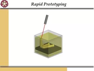
Multiplication UM* ( u1 u2 -- upL upH ) T N N2 : UM* ( u1 u2 - upL upH ) 0 mpp mpp mpp mpp mpp mpp mpp mpp mpp mpp mpp mpp mpp mpp mpp mpp ROT_DROP ; mpp (multiply partial product) if N(0) = 1 then adsh else sh end if; : * ( n1 n2 – n1*n2 ) UM* DROP ;
Division shldc sll T & N; if T[16:8] > N2 then T := T - (0 & N2); N(0) := ‘1’; end if; Dividend T N N2 Divisor
32 / 16 = 16:16 Unsigned Division : UM/MOD ( unL unH un -- ur uq ) -ROT shldc shldc shldc shldc shldc shldc shldc shldc shldc shldc shldc shldc shldc shldc shldc shldc ROT_DROP_SWAP ;
32 / 16 = 32:16 Unsigned Division : MU/MOD ( ud un -- urem udquot ) >R 0 R@ \ udL udH 0 un UM/MOD \ udL remH quotH R> \ udL remH quotH un SWAP >R \ udL remH un UM/MOD \ remL quotL R> ; \ remL quotL quotH
Name Function #ClkCyc DIO2@ Fetch the 8-bit byte from the DIO2 data bus and load it into T. 1 DIO2! Store the byte in N at the DIO2 address in T. Pop both T and N 3 LCDinst! Write instruction in N to the DIO2 LCD. 8 LCDdata! Write data in N to the DIO2 LCD. 8 JMP Jump to inline address 2 JZ Jump if all bits in T are ‘0’ and pop T 2 DIO2 and Transfer Instructions
LCD.WHP HEX : 1ms_Delay( -- ) 30D1 FOR NEXT ; : 30ms.Delay ( -- ) 1E FOR 1ms_Delay NEXT ; : lcd.init ( -- ) 30ms.delay 3C 0 LCDinst! \ 2 x 40 display 1ms_Delay 0f 0 LCDinst! \ display on 1ms_Delay 1 0 LCDinst! \ display clear 1ms_Delay 1ms_Delay 6 0 LCDinst! \ entry mode 1ms_Delay ;
LCD.WHP (cont.) : clear.lcd( -- ) 1 0 LCDinst! \ display clear 1ms_Delay 1ms_Delay ; : crlf.lcd( -- ) C0 0 LCDinst! \ set address 40 1ms_Delay 1ms_Delay ; : hex2asc ( n -- asc ) F AND \ mask upper nibble DUP 9 > \ if n > 9 IF 37 + \ add $37 ELSE 30 + \ else add $30 THEN ;
LCD.WHP (cont.) : hex>lcd ( hex -- ) hex2asc 0 LCDdata! 1ms_Delay ; : u.lcd ( u -- ) DUP C RSHIFT hex>lcd DUP 8 RSHIFT hex>lcd DUP 4 RSHIFT hex>lcd hex>lcd ;
A simple decimal calculator HEX : get.dec ( -- n k ) \ k = non-dec key 0 \ decimal # n in hex BEGIN waitBTN2 but>num \ press button DUP A < \ while 0 - 9 WHILE DUP hex>lcd \ display on lcd SWAP A * + \ convert to hex REPEAT ; : display.dec( ud -- ) 1 >R \ save count BEGIN A MU/MOD OVER OVER XOR WHILE \ while dquot <> 0 R> 1+ >R \ inc count REPEAT DROP DROP \ drop 0 0 R> \ get count FOR hex>lcd \ display all digits NEXT ;
: main( -- ) lcd.init BEGIN BEGIN get.dec \ enter decimal number DUP E = \ followed be E key WHILE clear.lcd DROP REPEAT DUP C = \ press C key to IF DROP UM* \ multiply clear.lcd display.dec \ display product ELSE DUP D =\ press D key to IF DROP 0 SWAP UM/MOD \ divide clear.lcd 0 display.dec \ display quotient crlf.lcd 0 display.dec \ display remainder ELSE B = \ press B key to IF DROP clear.lcd \ clear the display THEN THEN THEN AGAIN ; A simple decimal calculator (cont.)
16x2 character LCD • Four seven segment displays • 16 LEDs in three colors • 8 switches • 15 pushbutton keypad • 8-bit VGAport • PS/2 port Digilab IO2 Board
Summary • A Forth core has been implemented on a Xilinx Spartan II FPGA • This Forth core allows rapid prototyping of the Digilent DIO2 board • Easy access to the LEDs, 7-segment displays, LCD display, switches, and pushbuttons • Demonstrated by implementing a simple decimal calculator