Download
1 / 60
600 likes | 732 Views
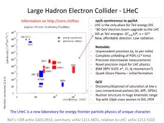
Large Hadron electron Collider - LH e C Frank Zimmermann UPHUK-4, Bodrum, 31 August 2010. 4. Uluslararası Katılımlı Parçacık Hızlandırıcıları ve Uygulamaları Kongresi (UPHUK4) 30 Ağustos-1 Eylül 2010. outline. physics motivation target parameters Linac-Ring & Ring-Ring options

E N D
Large Hadron electron Collider - LHeCFrank ZimmermannUPHUK-4, Bodrum, 31 August 2010 4. Uluslararası Katılımlı Parçacık Hızlandırıcıları ve Uygulamaları Kongresi (UPHUK4) 30 Ağustos-1 Eylül 2010
outline • physics motivation • target parameters • Linac-Ring & Ring-Ring options • e+source options • p beam parameters • IR design • e- beam parameters, e- RLA/ERL layouts • LHeC-CLIC • high-energy ERL option • tentative schedule, conclusions
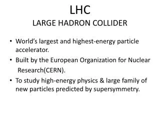
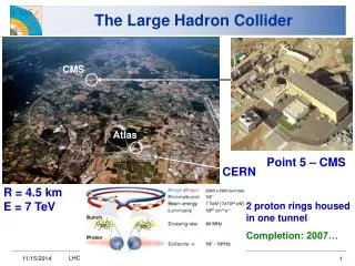
LHeC– Large Hadron electron Collider • motivation: • rich physics program: e-q physics at TeV energies • precision QCD & electroweak physics • boosting precision and range of LHC physics results • beyond the Standard Model • high density matter: low x and eA, & also gA collisions • Tevatron/LEP/HERA (Fermiscale) LHC/LC/LHeC (Terascale) • 100 fold increase in luminosity, in Q2 and 1/x w.r.t. HERA • status: • CERN-ECFA-NuPECC workshops (2008, 2009, 2010: 28.-30.October) • Conceptual Design Report in print by spring 2011
LHeC - more physics motivation >5x HERA c.m. energy >>10x HERA luminosity Max Klein & Paul Newman, CERN Courier April 2009 Max Klein & Paul Newman, CERN Courier April 2009 energies and luminosities of existing and proposed future lepton-proton scattering facilities e- energy ~60-140 GeV luminosity ~1033 cm-2s-1 distance scales resolved in lepton-hadron scattering experiments since 1950s, and some of the new physics revealed
kinematic plane in Bjorken-x and resolving power Q2, showing the coverage of fixed target experiments, HERA and LHeC >> 10x particle physicists request both e-p &e+p collisions; lepton polarization is also “very much desired” Max Klein & Paul Newman, CERN Courier April 2009
LHeC – several options RR LHeC: new ring in LHC tunnel, with bypasses around experiments RR LHeC e-/e+ injector 10 GeV, 10 min. filling time LR LHeC: recirculating linac with energy recovery, or straight linac
this talk will focus on “linac” options • least interference with LHC infrastructure • compatible with LHC energy upgrade • upgrade potential to higher energy or to LC • lots of synergies with CLIC, ILC and SPL however LR LHeC is not the baseline or not yet
LHeC-RR & LHC interferences „About 350 places to be avoided for e-magnets. Some areas very difficult. Solutions will be looked for, once a solution for the other ~350 obstacles has been found. Note: The experiments 1 and 5 are passed on the outside. That increases the overall length. [beware of Hirata-Keil beam-beam resonances!] We have to cross the transport region to compensate the overlength. This is almost impossible, because it would make any accelerator repair even more difficult.“ K.-H. Mess, February ‘10
Hirata-Keil resonances: beam-beam resonances for circumference ratio K+/K-≠1 K. Hirata and E. Keil, 1990; compare also overlap knockout resonances at CERN ISR (S. Myers) → dense net of resonances in tune space if circumferences are slightly different → spontaneous beam separation
Large Hadron electron Collider -Linac-Ring options J. Osborne
L-R LHeC – collaborating institutes TOBB ETU KEK
LHeC LR design contributors S. Bettoni, C. Bracco, O. Brüning, H. Burkhardt, E. Ciapala, B. Goddard, F. Haug, B. Holzer, B. Jeanneret, J. Jowett, J. Osborne, L. Rinolfi, S. Russenschuck, D. Schulte, H. Thiesen, R. Tomas, F. Zimmermann, CERN, Switzerland; C. Adolphsen, M. Sullivan, Y.-P. Sun, SLAC, USA; A.K. Ciftci, R. Ciftci, K. Zengin, Ankara U.,Turkey; H. Aksakal, Nigde U.,T.; E. Eroglu, I. Tapan, Uludag U., Turkey; T. Omori, J. Urakawa, KEK, Japan ; S. Sultansoy, TOBB, Turkey; J. Dainton, M. Klein, Liverpool U., UK; A.Variola, LAL, France; R. Appleby, S. Chattopadhyay, M. Korostelev, Cockcroft Inst., UK; A. Polini, INFN Bologna, Italy; E. Paoloni, INFN Pisa, Italy; P. Kostka, U. Schneekloth, DESY, Germany; R. Calaga, V. Litvinenko, V. Yakimenko, BNL, USA; A. Eide, NTNU, Norway ; A. Bogacz, JLAB, USA more are welcome!
performance targets e- energy ≥60 GeV luminosity ~1033 cm-2s-1 total electrical power for e-: 100 MW e+p collisions with similar luminosity simultaneous with LHC pp physics e-/e+ polarization detector acceptance down to 1o getting all this at the same time is very challenging
Flux of e+ L. Rinolfi, May 2010 X 18 X 6666 X 65 quite a challenge!
e+ source options • Compton ring • Compton ERL • Compton linac • undulator based source • e- beam on liquid metal-jet target • e+ recycling
Compton Ring and Compton ERL (ILC) T. Omori, L. Rinolfi, J. Urakawa et al
Compton Linac for e+ source ~5 ns 312 pulses Ng / Ne- = 1 (demonstrated at BNL) Ne+ / Ng = 0.02 (expected) i.e. 50 gammas to generate 1 e+ Data for CLIC: Ne+ = 6.4 x 10⁹ / bunch ~ 1 nC Ne- = 0.32 x 10¹² / bunch ~ 50 nC 4 GeV With 5 nC / e- bunch and 10 Compton IP's => 1 nC / e+ bunch For LHeC, one would need to increase the number of targets/capture sections working in parallel in order to reach the requested intensity. => Cost and reliability issues T. Omori, L. Rinolfi, J. Urakawa et al
LHeC e+ source based on undulator e- Linac e+ pre-Linac e- IP 1 spent e- Undulator g Target LHC p+ e+ Linac e+ L. Rinolfi et al
high-power e- beam on liquid-metal target V. Yakimenko, June 2010 - CERN “Merit” (liquid Hq droplet target): possibility to handle MW beam. - Tokyo University S-band gun generating 3nC every 2.8ns for 100 bunches and plan to go up to 1000 bunches LHeC proposal: send ~1 MW average power e- beam on liquid target ~100 Hz, ~1 ms trains, 1 A average over macro pulse, 100 mA average current; e+/e- yield > 1 with small transverse emittance total wall plug power for e+ source ~3-5MW cost estimate) ~50M$ concern: stability of “droplet” during macropulse 1 MW e- beam e+ liquid metal target
how do we get 1033 cm-2s-1? luminosity of LR collider: (round beams) average e- current ! • maximize geometric • overlap factor • head-on collision • small e- emittance take highest proton beam brightness permitted by LHeC management (“ultimate” LHC values) • assume smallest conceivable • proton b* function: • reduced l* (23 m → 10 m) • squeeze only one p beam • new magnet technology Nb3Sn
proton beam brightness Nb,p/ep management decision proton bunch spacing (which multiple of 25 ns) is irrelevant for LHeC!
proton round-beam IR optics for ultra-low b* l*=10 m R. Tomas extended e- final-focus optics by Kahraman Zengin, Ankara U.
new flat p-p HL-LHC optics w low b* & l*=23 m squeezed optics: b*x/y = 7.5/30 cm (flat beam) alternated in IR1&5 barc increased by a factor of 2 or 8 in s45/56/81/12 depending on the b* aspect ratio in IP1 and IP5 this flat-beam optics is alternative for LHeC S. Fartoukh
geometric reduction factor C. Adolphsen H. Braun F. Zimmermann (round beams) geometric loss factor Hhg vs. crossing angle LHeC working point bp*=10 cm
interaction region (2008) R. Tomas, F.Z. or return loop small e- emittance → relaxed be* → Le* > Lp*, can&must profit from ↓bp* ; single pass & low e-divergence → parasitic collisions of little concern; → head-on e-p collision realized by long dipoles
IR layout w. head-on collision detector integrated dipole: field ~0.45 T critical photon energy ~ 1 MeV average SR power = 87 kW 8x10¹⁰g / bunch passage is the SR acceptable for the detector? beam envelopes of 10s (electrons) [solid blue] or 11s (protons) [solid green], the same envelopes with an additional constant margin of 10 mm [dashed], the synchrotron-radiation fan [orange], and the approximate location of the magnet coil between incoming protons and outgoing electron beam [black]
prize questions can we shield the SC proton quadrupole from MeV synchrotron radiation? - “this SR is very difficult to shield” K.-H. Mess, LHeC Divonne 2008 - studies by Husnu Aksakal (2009) and Emre Eroglu (2010) can we reduce back-scattering into the detector to an acceptable level? - studies by Kenan and Rena Ciftci (2010)
SR shielding - FLUKA simulation example FLUKA results [GeV/cm3] 30 cm shielding is enough SR code (linked to FLUKA) calculates #SR photos per m, per energy bin lead shielding in front of triplet vacuum dipole Husnu Aksakal, Nigde U., 2009
LEAD (Pb) Emre Eroglu, Uludag U., 2010 FLUKA simulation Energy deposition in lead target. Max. value is 0.152 GeV/cm3/g For 25 cm of lead no SR photon penetrates through the target. again 30 cm shielding is enough
Emre Eroglu, Uludag U., 2010 back scattering of e- and e+from lead target e- FLUKA simulations Max. energy is about 0.103 Gev/cm3/g for electron (up), and about 0.075 GeV/cm3/g for positron (down). e+
LEAD (Pb) Emre Eroglu, Uludag U., 2010 g Back scattering of g’s from lead target. Max. energy is about 0.242 GeV/cm3/g for photon
reflection of g’s by mirrors Kenan & Rena Ciftci, Ankara U., 2010 Surface of the magnet-coil protection shield should be sloped to reduce power density. Acceptable: ~10-20 W/mm2. Proposal: introduce mirrors with a shallow grazing angle to reflect part of the photons into electron beam channel or special SR extraction holes
“supercon” type magnet p e- d~8.7 cm gradient ~250 T/m Nb-Ti ~310 T/m Nb3Sn S. Russenschuck
“mirror” half quadrupole magnet p e- d~6.3 cm gradient ~145 T/m Nb-Ti ~175 T/m Nb3Sn S. Russenschuck
detector integrated dipole SC solenoid coil B IP SC coil split and tilted B Stephan Russenschuck, Simona Bettoni, Eugenio Paoloni
how about 2nd LHC proton beam? • 2nd beam must be transported across LHeC IR • two possibilities: • common IR vacuum chamber; second beam unsqueezed • (2) detector with a bypass hole (c.f. Tevatron D0)
we did what we could on p side how about e-? e- emittances and b* not critical(protons are big, ~7mm!) most important parameter: average beam current in addition: bunch structureand polarization
target luminosity we need about 6 mA CLIC design current ~ 0.01 mA (factor 600 missing) lowering voltage, raise bunch charge & rep rate → 0.06 mA (NIMA 2007) CLIC drive beam ILC design current ~ 0.05 mA (factor ~100 missing)
SC linacs can provide more average current at lower energy (& lower gradient) e.g. by increasing the duty factor 10-100 times, or even running cwexample design average currents:CERN HP-SPL: ~2.5 mA (50 Hz)Cornell ERL ~100 mA (cw)eRHIC ERL ~ 50 mA at 20 GeV (cw)LHeC ERL needs 6 mA at 60 GeV
LHeC ERL site power main contributions: RF power dissipation + RF power to compensate ERL inefficiency Cryo power for SC linac (RF gradient) SR energy losses in return arcs (radius) g: gradient E:final energy D:duty factor A, B and C: coefficients r: bending radius
one more ingredient! • choice of SC linac RF frequency: • 1.3 GHz (ILC)? • ~700 MHz! • requires less cryo-power (~2 times less from BCS • theory); true difference ↔ residual resistance, • [J. Tückmantel, E. Ciapala] • synergy with SPL, eRHIC and ESS
LHeC –Linac-Ring configurations p-60 erl 10-GeV linac LHC p injector 1.67 km dump 0.34 km 1.0 km injector 30-GeV linac IP dump 2.0 km LHC p “least expensive" p-140 10-GeV linac IP high luminosity 2.0 km LHC p 3.9 km injector IP dump 70-GeV linac p-140’ 7.8 km high energy IP 140-GeV linac dump injector
LHeC – general parameters • $smaller LR p-b* value than for • nominal LHC (0.55 m): • reduced l* (23 → 10 m) • only one p beam squeezed • new IR quads as for HL-LHC B. Holzer, M. Klein, F. Zimmermann
example (old) RLA optics for 4-pass ERL option w. 500 MeV injection energy (=dump energy) new optics under development by Alex Bogacz (JLAB) LHeC question: feeding groups of linac quadrupoles by one power converter? or no quads?! Vladimir Litivinenko Anders Eide Hugues Thiesen 0.5→ 31.25 → 60 → 31.25→ 0.5 GeV
details of return loop design LHeC questions: same power converter feeding magnets for several loops with different number of coils or separate power converter for each loop? strength of dipoles and quad’s tapered to local beam energy (SR)? Hugues Thiesen common vacuum chamber for eRHIC return loop with several layers of small-gap magnets, profiting from small e- emittance W. Meng et al PAC’09
SR & chromatic emittance growth Y.-P. Sun SR emittance growth: few % at 60 GeV, & 100% at 140 GeV SR emittance growth OK! ge=100 mm at 140 GeV and 50 mm at 60 GeV are conservative values Relative emittance for three final beam energies (60 GeV, 100 GeV and 140 GeV); here test initial emittance is 2 μm. For E = 140GeV, the absolute normalized emittance growth is roughly 50 μm, which was confirmed by other simulation studies with higher start emittance & by analytical estimates
ERL collective effects multi-beam wakes & beam break up modified PLACET code (D. Schulte) ion accumulation and ion-driven instabilities needs gaps and/or clearing electrodes electron-cloud instability for e+ beam simulations planned (G. Rumolo)