Download
1 / 12
120 likes | 188 Views
Working with the RAPID-CIM Software. Dr. Richard A. Wysk Industrial and Manufacturing Engineering PSU. Outline. Overview of software architecture Control software development process MPSG controller development MPSG graph->MPSG input file->code MPSG Builder Specifications

E N D
Working with the RAPID-CIM Software Dr. Richard A. Wysk Industrial and Manufacturing Engineering PSU
Outline • Overview of software architecture • Control software development process • MPSG controller development • MPSG graph->MPSG input file->code • MPSG Builder Specifications • Shop Control software customization • extra message info • Equip. Control software customization • machine interfacing logic, RS-232, digital I/O • DEMO !
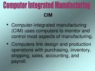
Software Architecture Real Time Simulation Controller Database : Process Plans Part Orders Executes process plan sequence, allocates resources to production of part, sends messages to shop controller. Ethernet socket connection Distributes messages to appropriate equipment, coordinates synchronous picks and puts based on shop level state graph. Shop Controller Ethernet message router Issues hardware commands based on shop level instructions. Follows equipment level state graph. Kardex ABB Robot VF-O SL-20 RS-232, Digital I/O Hardware
Software Architecture Real Time Simulation Controller Database : Process Plans Part Orders Executes process plan sequence, allocates resources to production of part, sends messages to shop controller. Ethernet socket connection Distributes messages to appropriate equipment, coordinates synchronous picks and puts based on shop level state graph. Shop Controller Ethernet message router Issues hardware commands based on shop level instructions. Follows equipment level state graph. Kardex ABB Robot VF-O SL-20 RS-232, Digital I/O Hardware
Generate shop level software, add customization for extra msg info Design shop control part state graph based on general assumptions Define extra message info for equipment VERIFY ! by hand Design equipment control part state graphs based on expected resource interaction with part. Generate equip level software, add customization for hardware interfacing VERIFY ! with manual control of shop controller Control software development process General principle: design control software to be generic, verify with specific parts.
Procedures for Part Processing Detailed Model for PSU Wysk, Peters, Smith Model Start Start Buf. Release Tray Unload End NS Unload Load NS Load Buf. Return Tray MP Release Part MT Move Process/Store Synch Load End Unload MP Grasp Part Load MP Process Move Synch Unload
Some assumptions for PSU • Always non-synchronous load to and unload from MT and BS devices. • Always synchronous load to and unload from MP devices. • Part always starts and ends at a BS device.
MPSG Controller Development Visual C++ Project header file code file action file MPSG Input File MPSG Graph MPSG Builder manual manual modification generic files extra message info handling (i.e. NC/robot file names) manual modification hardware interface customization
MPSG Builder Specifications • See handout for Input File Specification • Output Files: • header file: defines constants used by code • code file: functions to initialize state graph and parse input messages • action file: task precondition and action functions (modifiable by you) • Note: precondition functions not designed for error-handling, simply re-execute until precondition is satisfied (function returns TRUE).
Shop Control software customization • Shop control software task action functions get messages from simulation and pass them to equipment controllers. • Code to pass along extra message info (i.e., NC/robot files names) must be explicitly added in action function.
Equip. Control software customization • Not required for simulated testing. • Required to interface with hardware. • Add interfacing C code to appropriate task action functions (i.e., grasp, process, etc). • Serial DLL for RS-232 communication (Kardex, Puma robot, download NC files). • Device Driver for digital I/O communication using digital I/O board (PLC interfacing, interfacing to relays, digital switches).
put load process clear2 clear1 release pick pick_br put_br 1 3 9 8 5 6 7 4 6 3 2 11 7 10 12 0 5 2 1 9 4 8 0 T I I T T T T T T unload_bm process_bm load_ok_bm process_ok_bm unload_ok_bm load_bm I O I O I O DEMO ! Generic MH graph pick_ok_br clear1_ok_br put_ok_br clear1_br O I O O clear2_br I clear2_ok_br O Generic MP graph