Download

1 / 17
170 likes | 253 Views
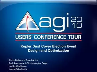
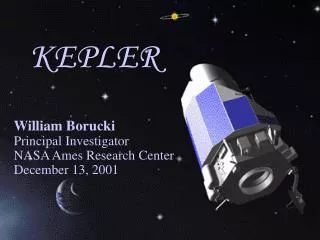
Kepler Dust Cover Ejection Event Design and Optimization. Chris Zeller and David Acton Ball Aerospace & Technologies Corp. czeller@ball.com dacton@ball.com. Outline. Kepler mission overview Summary of problem How and why project used AGI software Optimizing dust cover release attitude

E N D
Kepler Dust Cover Ejection EventDesign and Optimization Chris Zeller and David Acton Ball Aerospace & Technologies Corp. czeller@ball.com dacton@ball.com
Outline • Kepler mission overview • Summary of problem • How and why project used AGI software • Optimizing dust cover release attitude • Key risk reductions from using AGI software
Kepler mission overview Planet transit • NASA mission launched March 2009 • Search for Earth-size planets • In/near habitable zone of solar-like stars • Highly sensitive photometer • Continuously and simultaneously measures brightness of >100k stars • Flight segment design and fabrication at Ball Aerospace & Technologies Corp. • Scientific Operations Center at NASA Ames Research Center • Mission Operations Center at LASP – University of Colorado Variation in star brightness indicates planet transit
Summary of problem • Ensure ejected photometer dust cover (DC) does not return to strike flight segment (FS) • Determine release attitude to maximize FS-to-DC distance over mission duration • Must meet power, telecom, and sun-avoidance constraints • Ensure validity of solution considering uncertainties • DC ejection direction and velocity • DC surface properties • DC release date
Kepler trajectory description • Helio-centric Earth-trailing orbit avoids obscurations • ~0.5 AU range from Earth after 4 years • No traditional V maneuvers required • Periodic reaction wheel desaturations • Via RCS thruster pulses • Small but measurable effects on trajectory • STK excellent modeling fit
Dust cover design and release • Protects photometer • Contamination prior to, and during launch • Stray/direct sunlight during launch and early commissioning • Deployment mechanism • Single latch, single fly-away hinge, and pre-loaded screws • Nominal release • Along vector ~ 8º from sunshadenormal, towards hinge side • Relative velocity ~0.5 m/sec • Variations must be considered • Constraints on release attitude • Power • Telecom • Photometer Sun-Avoidance
STK allowed efficient and accurate analysis for important Kepler issues • STK as standard trajectory modeling and analysis tool • Chosen early in the project • Ease of use, flexibility, visualization, accuracy, and familiarity to analysts • Used for a variety of analyses • Power estimates, telecom range and angles for duration of mission • Initial Acquisition timing and angles • Deep Space Network station view periods • Optimization of quarterly roll windows • Verification of commissioning attitudes • Dust Cover Ejection event (this presentation) • Allowed validation of similar customer analyses • This analysis – STK Professional, Astrogator, Chains, and Analyzer • Astrogator provided unique features to tailor deep space analysis
Baseline trajectory model • Trajectory modeled using Astrogator • Initial conditions at launch vehicle separation • Near-Earth perturbations with Earth-moon gravity model • Dust cover separation reaction modeled as a maneuver • Desaturation burns (every 3 days) using sequence loops • Deep Space propagation (6 years) Kepler-Earth body-body rotating reference frame
Validation of the STK Kepler model • Validated model with JPL Navigation Team’s MONTE Tool • Tailored Astrogator propagator to determine which physics to model • Updated STK to latest planetary ephemeris to match JPL inputs • Final result – highly accurate STK trajectory model Range Difference Between JPL and STK Solutions • Selected Propagator: • Earth J2 with Moon + Sun 3rd bodies • Heliocentric + all 9 planets after • 9.25E+5 km from Earth Range (km) • Alternate Selection: • Earth HPOP + • Sun/moon 3rd bodies • Heliocentric + all 9 • planets after 9.25E+5 • km from Earth Days After Release Validation was essential to provide customer confidence in solution
Features of the dust cover ejection model • Coordinate system selected for fixed attitude with respect to Sun • Provided fixed constraints for photometer sun-avoidance & power • STK Vector Geometry Tool validated antenna, star tracker, photometer FOV constraints • Target pointing attitude selection used to determine release attitude • Baseline DC trajectory returned towards FS several times • Oscillatory behavior • Suggested we perform optimization and sensitivity analyses VNC(Sun) = Velocity, Normal, Co-Normal, centered on Sun
Analyzer Carpet Plot was generated tooptimize release directions • Appropriate Figure-of-Merit was crucial • Oscillatory behavior of DC motion required careful FoM choice • FoM chosen as minimum range after initial “drift-away” period Note: Not all options were good ones
Optimum release direction • Optimal release direction maximized minimum range • But did not meet Earth and Sun constraints • Selected next best option • Nominal minimum range after drift away is 40,820 km • Desaturation impulses help • Tend to push FS away from DC over time • Attitude computation • Target Pointing attitude and custom reports used to compute VNC-Body quaternion
Sensitivity analysis using Analyzer • Monte Carlo tool to investigate variations in parameters • Release angle, release velocity, and DC reflectivity • Verified large minimum range met under even 3 conditions • Reduced risk that inaccuracy in any one parameter could throw us “off the cliff”
Sensitivity analysis for DC release date • Reduce impact of commissioning schedule changes • Necessary to run manually • Analyzer could not handle variations in epoch dates • Determined release date variations acceptable • Within range of dates considered Dust cover successfully released on April 8, 2009 Worst Case DC-FS range > 40,000 km
STK provided key risk reduction for dust cover ejection • STK allowed efficient analyses of complex problem • Reduced cost and time to address important Mission Design concern • Ability to fine-tune trajectory estimates during independent validation with customer solutions lowered risk of errors • Cost-benefit of Analyzer was important • Significantly reduced time for optimization and Monte Carlo analyses • 3D visualization provided simple visual verification of all results • Lowered risk of violating flight rules • Easy to communicate results across program and to stakeholders
Acknowledgements • AGI Tech Support • For their helpful dedication and long hours helping sort out the best way to approach the problem • Jeff Baxter • Dana Oberg • Luis Montano • Ball Aerospace colleagues • For their insightful consultation • Scott Mitchell • Adam Harvey
Contact information • Chris Zeller • Senior Systems Engineer • Ball Aerospace & Technologies Corp. • Boulder, Colorado • czeller@ball.com • 303-939-4636 • David Acton • Senior Systems Engineer • Ball Aerospace & Technologies Corp. • Boulder, Colorado • dacton@ball.com • 303-939-4775