Download
1 / 32
320 likes | 497 Views
Electron Dynamics at Metal Surfaces. Fulvio Parmigiani. Università degli Studi di Trieste Dipartimento di Fisica and Sincrotrone Trieste (Trieste, Italy). Introduction.

E N D
Electron Dynamics at Metal Surfaces Fulvio Parmigiani Università degli Studi di Trieste Dipartimento di Fisica and Sincrotrone Trieste (Trieste, Italy)
Introduction The study of the electron dynamics at surfaces and interfaces relays on the ability to time-resolve the ultra-rapid scattering processes which result in energy and momentum relaxation, recombination and diffusion. In typical experiments a short-pulsed (10-100 fs) laser can be used for photoemission experiments in the time-domain, whereas longer laser pulses (1-5 ps) provided by FT limited coherent sources can be used for photoemission experiments in the frequency (energy) domain with unrecorded resolving power. Experimental techniques must be brought to bear in which band-structure specificity are combined with time resolution. Angle resolved photoemission is particularly suited for such experiments.
Introduction • A rather interesting system to study the electron dynamics at the solid surfaces is represented by the Surface States (SS) Image Potential States (IPS). • The SS-IPS represents a paradigmatic two-levels system in solids and can be seen as a playground to study, in the momentum space,the optical transitions in semiconductors, insulators and superconducting systems. • band dispersion • direct versus indirect population mechanisms • polarization selection rules • effective mass ( in the plane of the surface) • electron scattering processes and lifetime
Introduction ToF TIME RESOLVED MULTI-PHOTONPHOTOEMISSION (hn<F) band mapping ofUNOCCUPIED STATES and ELECTRON SCATTERING PROCESSES mechanisms LINEAR PHOTOEMISSION (hn>F) band mapping of OCCUPIED STATES
Introduction Linear photoemission on Ag(100) h=6.28 eV Multiphoton on Ag(100) h = 3.14 eV n=1 n=2 M-B distribution “temperature” in a typical range of 0.5-0.7 eV. G. P. Banfi et al., PRB 67, 035418 (2003). PHOTOEMISSION SPECTRA ON Ag(100) p-polarized incident radiation 30° incidence and 150 fs pulse. F-D distribution at the RT energy Log Scale 106 sensitivity Iabs=13 mJ/cm2
Experimental Set-up ToF sample detector Acceptance angle: 0.83° Energy resolution: 10 meV @ 2eV Detector noise: <10-4 counts/s PS1 PS2 PS3 PS4 PC Preamplifier Discriminator GPIB Multiscaler FAST 7887 stop start Laser • m-metal UHV chamber • residual magnetic field < 10 mG • Base pressure <2·10-10 mbar • photoemitted electrons detector: • Time of Flight (ToF) spectrometer G. Paolicelli et al. Surf. Rev. and Lett. 9, 541 (2002)
Evac n=1 Φ empty states Efermi occupied states g = Non-Linear Photoemission Process • PHOTOEMISSION PROCESS • PROBLEMS: Upon the absorption of two photon the electron is already free. Which is the absorption mechanism responsible of the free-free transition? Keldysh parameter g=1500>>1, perturbative regime Evidence of ABOVE THRESHOLD PHOTOEMISSION in solids ?
2 and 3 photon Fermi Edge: - DE = hn - Fermi-Dirac edge Non-linearity order: 3-photon Fermi edge vs 2-photon Fermi edge n=3 n=2 Energy-shift with photon energy: DE3PFE = 3·hDn ATP 3-Photon Fermi Edge: Three experimental evidences...
ATP Evac n=1 Φ empty states Efermi Rough Estimate T(3)/T(2)10-6 Experimental Value T(3)/T(2)10-4 occupied states Is another mechanism involved? • PHOTOEMISSION PROCESS • RESULTS: To evaluate the cross sectionfor an n-photon absorption involving the initial and final states: is proportional to the Transition Matrix Element in the DIPOLE APPROXIMATION In this calculation we have to consider the mixing of the final free electron state with all the unperturbed Hamiltonian eigenstates but is it difficult to evaluate the contribution of this mixing to T(3).
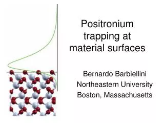
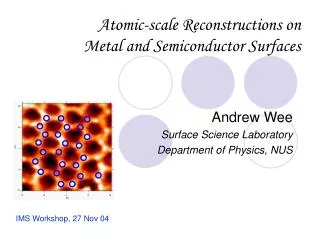
Image Potential States Ag(100) U. Hofer et al., Science277, 1480 (1997). In most metals exists a gap in the bulk bands projection on the surface. When an electron is taken outside the solid it could be trapped between the Coulomb-like potential induced by the image charge into the solid, and the high reflectivity barrier due the band gap at the surface.
k// Dispersion Image Potential States dispersion measured via two-photon resonant ARPES on Ag(100) along GX LEED n=1 n=2 IPS n=1: hn=4.32 eV, p pol. E m/m*=1.03 0.06 n = 2 m/m*=0.97 0.02 G. Ferrini et al., Phys. Rev. B 67, 235407 (2003) n = 1 k//
Undirectly Populated IPS on Ag(100) Photoemission Spectra on Ag(100) single crystal Evac n=1 p-polarized incident radiation ? F empty states Log Scale 106 sensitivity Efermi occupied states Iabs=13 mJ/cm2 Direct Photoemission Fermi Edge hn = 6.28eV Ekin= hn-F 2-Photon Photoemission with P-polarized light 2-P Fermi Edge hn = 3.14eV Ekin= 2hn-F hn
Image Potential State Shifting with photon energy hn2=3.54eV DEkin=0.39 eV hn1=3.15eV Ag(100) Ekin = hn-Ebin Ebin 0.5 eV n=1 K||=0
k// -dispersion of non-resonantly populated IPS 2DEG effective mass(ARPES) m/m* = 0.88 0.04, hn= 3.14 eVnon resonant excitation both in pand s polarizations m/m*= 0.97 0.02, hn = 4.28 eV resonant excitation, p-polarization 9% change of IPS effective mass suggests that the photoemission process is mediated by scattering with the hot electron gas created by the laser pulse. G. Ferrini et al., Phys. Rev. Lett. 92, 2568021 (2004).
Cu(111) LEED pattern Cu(111) n=2 EV GK GM Shockley state d-band Tamm states
Cu(111) IPS is located at k//=0 close to the upper edge of the bulk unoccupied sp-band (~200meV) The energy separation between the IPS and the occupied surface state n=0 (Shockley)is about 4.45 eV VL ≈ ≈ EF
m*/m measurements IPS (n=1) m*/m measurements on Cu(111) and Ag(111) Smith Goldmann Padowitz Haight Schoenlein Giesen
Phase shift model For the flux conservation Phase shift model - P.M. Echenique, J.B. Pendry- Reflected wave from the crystal surface: Reflected wave from the image potential barrier: In the phase-analysis model treats the states as electron waves undergoing multiple reflection between the crystal and image potential. Summing the repeated scattering gives the total amplitude ofy : a pole in this expression denotes a bound states of the surface, i.e. a surface states the condition for a surface state is N.V. Smith, PRB, 32,3549(1985) Bohr-like quantization condition on the round trip phase accumulation J.Phys.C:Solid State Phys., 11, 2065 (1978)
Phase shift model wave function outside the crystal wave function inside the crystal momentum perpendicular to the surface where q is the damping factor The wave functions Even though completely reflected, the wave does extend to the far side of the boundary as the evanescent wave Unoccupied bands GAP N.V. Smith, PRB, 32,3549(1985)
Phase shift model The phases For a pure image potential, the barrier phase change may be written In the nearly-free-electron two band model kis the electron momentum at k//=0 z0 is the position of the image potential plane The phaseFBfor an image barrier divergesequation is satisfied ad infinitum, Rydberg series are generated, converging on the vacuum level The phaseFBchange respect to the energy is connected to the penetration of the wave on the vacuum side of the boundary. The phaseFCchange respect to the energy is connected to the penetration of the wave in the crystal
Phase shift model For infinite crystal barrier En When Ev is in the gap perfect reflectivity non perfect reflectivity FC= p FC< p a = 0 a ≠ 0 TheFCphase K. Giesen, et al., PRB, 35, 975 (1987) If FCis treated as a constant over the range of the Rydberg series the energies are given by m free electron mass; n =1, 2, 3… K// ( Å-1) is the quantum defect P.M. Echenique, Chemical Physics, 251, 1 (2000)
Phase shift model on Ag(111) on Cu(111) IPS effective mass on Cu(111) in the phase shift model At different k// the electron reflected by the surface experiences different phase change An effective mass m*/m different from unit results when the phaseFCand, consequently En, depends on k//. K// ( Å-1) K. Giesen, et al., PRB, 35, 975 (1987)
Cu(111) 60 meV Resonant Case Vacuum level hn=4.45 eV Fermi Energy The effective mass of the IPS and SS states are in agreement with the litterature.
Cu(111) Changing FC hn=4.71 eV m*/m=2.17 ± 0.07 in k//[-0.12, 0.12] m*/m=1.28 ± 0.07 in k//[-0.2, 0.2] hn = 4.71 eV To be submitted
Cu(111) FWHM 3-PPE
Cu(111) hn=4.28 eV Vacuum level hn=4.28 eV Fermi Energy
Cu(111) Dependence of m/m* on the pump intensity hn=4.71 eV hn=3.14 eV hn=4.71 eV To be submitted
unoccupied sp bands unoccupied sp bands B A B A IPS IPS k// k// Cu(111) hn=4.71 eV
Conclusions • ATP on solid was demonstrated • Indirect population of the IPS was shown • The origin of anomalous electron effective mass for the IPS has been clarified • The possibility to photo-induced changes of the electron effective mass in solids has been demonstrated.
Co-workers: G. Ferrini C. Giannetti S. Pagliara F. Banfi (Univ. of Geneve) G. Galimberti E. Pedersoli D. Fausti (Univ. of Groningen)