Download
1 / 16
160 likes | 321 Views
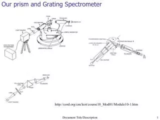
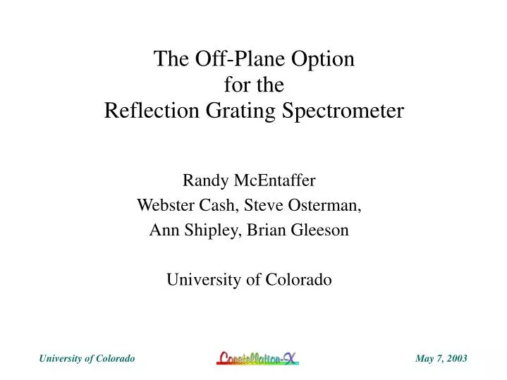
The Off-Plane Option for the Reflection Grating Spectrometer. Randy McEntaffer Webster Cash, Steve Osterman, Ann Shipley, Brian Gleeson University of Colorado. Off-plane Mount. In-plane Mount. Radial Groove Gratings. Off-plane Grating Module Locations on Envelope. R450.0mm Inner Mirrors

E N D
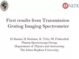
The Off-Plane Optionfor theReflection Grating Spectrometer Randy McEntaffer Webster Cash, Steve Osterman, Ann Shipley, Brian Gleeson University of Colorado
Off-plane Mount In-plane Mount
Off-plane Grating ModuleLocations on Envelope R450.0mm Inner Mirrors High Energy Grating Modules R770.0mm Outer Mirrors Grating Area R151.4mm
Off-plane Tradeoffs CON PRO • Higher Groove Density • Higher Throughput • Higher Resolution • Better Packing Geometry • Looser Alignment Tolerances
10,000 O-P n=3 O-P n=2 O-P n=1 Mission Requirement E/dE 1000 100 0.1 1.0 10.0 Energy (keV) Primary Response <35% Response Resolution Extended CCD ASSUMPTIONS: 5500g/mm 15” SXT 2” gratings 2” alignment Calorimeter – 2eV Mission Goal I-P n=1 Mission Requirement I-P n=2
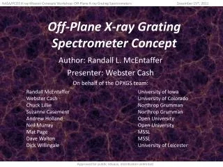
Effective Area 5000 ASSUMPTIONS: Coverage 40% of outer envelope Off-Plane Groove Efficiency 80% of theoretical 85% Structure Transmission CCD thin Al filter only • Goal 4000 off-plane 3000 cm2 2000 baseline 1000 Mission Requirement 0 0.1 1.0 10.0 Energy (keV)
Off-Plane Program • Optical Design – Projected Performance • Looks Attractive • Engineering Requirements • Has Significant Advantages • Grating Suppliers • Several Possible Suppliers • Holographic Techniques Look Better Than Mechanical • Grating Efficiency • Test Gratings at Colorado Now • Resolution Demonstration • Scheduled this Summer at Colorado • TRL Development • Plan to Achieve TRL 6
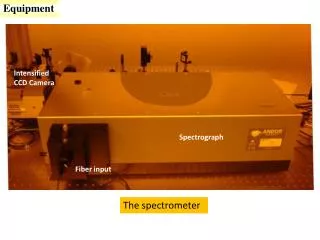
Grating Test Facility at CU Used for COS and FUSE
Grating #1 • Jobin-Yvon, radial grooves, 4246 g/mm, unblazed @ γ = 2º Absolute Efficiency: strongest order = 13% Sum orders = 29%
Grating #2 • Jobin-Yvon, radial grooves, 4246 g/mm, blazed 13º @ γ = 2º Absolute Efficiency: strongest order = 6.4% Sum orders = 11% 30% (w/ scatter)
Grating #3 • MIT, parallel rulings, 5000 g/mm, blazed 7º Groove eff. = Abs. eff./Reflectivity (a.k.a. Relative eff.)
Conclusion • Off-plane can significantly improve performance of Constellation-X RGS • Gratings can be built to required efficiency and scatter specifications • Resolution tests to be conducted this summer