Download
1 / 33
330 likes | 337 Views
Engineering Drawing Hand drawings to Solids Andrei Lozzi 2017.

E N D
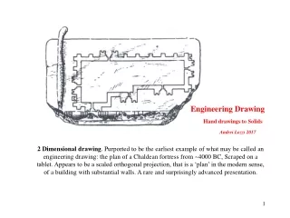
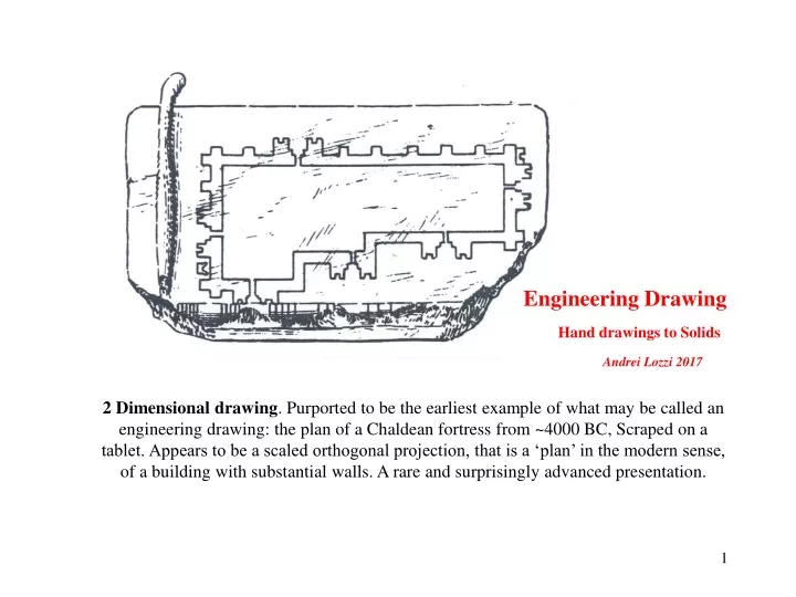
Engineering Drawing Hand drawings to Solids Andrei Lozzi 2017 2 Dimensional drawing. Purported to be the earliest example of what may be called an engineering drawing: the plan of a Chaldean fortress from ~4000 BC, Scraped on a tablet. Appears to be a scaled orthogonal projection, that is a ‘plan’ in the modern sense, of a building with substantial walls. A rare and surprisingly advanced presentation.
2 ½ Dimensional drawing. An Egyptian painting showing a large monument being moved. The size of the monument, number of rope handlers, water bearers, drummers and others appear to have been presented accurately. The style used in the construction of the drawing represents 2 dimensions reasonably well but depth is just implied.
3 Dimensional presentation. A ‘pictorial’ presentation of the disposition of the workers and machinery used in the erection of an obelisk in 1586 (but drawn in 1743). This drawing may give the impression of being a true perspective drawing it is close but it isn't quite. It appears to present faithfully the number and location of the workers and machinery used. That is, it tries to be an objective record of what and how the work was done. Hence it may be said to be an engineering drawing.
Begging with Gaspar Monge in the 1800s, engineers began to use versions of orthographic projections. It was established that all true lengths and angles could be represented by this sort of Two-Dimensional drafting method. These methods allow us to draw paradoxes, which may be resolved when drawn in Three-Dimensions.
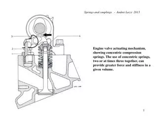
Perspective or Pictorial views A pictorial view, picture-like, maybe a perspective dwg or something simpler, makes the subject look realistic. The viewer can more readily comprehends the relationship of the parts to the whole. They can more quickly deduce how it may function, because it may look like similar items that the engineer is familiar with. This leads to fewer mistakes in handling. If little or no effect of perspective is shown then the parts are small. But significant perspective effect is present, then it indicates that the parts are large, like buildings. It is difficult if not impossible on such drawings to give exact information on the dimensions and method of manufacture. Pictorial drawings tend to be used to create subjective impressions not objective ones.
But Why SOLIDMODELLERS 3D – 2D Paradoxes It is all too easy to generate Impossible 3D items from possible 2D projections
Mr Escher used to mock our confidence in 2D drawings by showing that what in 2D could appear to be an impossible construction, could in fact be achievable, if thoroughly unorthodox in reality.
CODING SOLIDS The aim of solid modelers has been to overcome the limitations of WF (wire frame) CAD systems. WF present just lines and surfaces, requiring the reader to interpret them into real objects. WF can have many problems among these are disconnected elements and illegal (non 3D) solids. After many years of research only about 8 means to represents solid objects in software have been found to be possible and of these only about 6 of them at all practical. Of these some are simple and exact but can only describe simple solids. Others can deal with complex shapes but are almost never quite correct. The qualities that we require of solid model data bases (files) are that they be: Unique Verifiable Closed Accurate Compact & efficient
CSG - constructive solid geometry. Objects are arrived at by combining primitives using Boolean operations. The primitives may be many but usually include prisms, cylinders spheres and torusus. The primitives are solid shapes for which we have exact analytic expressions for their boundaries. These primitives may be merged and combined in a number of Boolean operations such that the final assembly can be completely and exactly described. Refs Computer Graphics, Foley, van Dam et al, Addison Wesley
Half Spaces. The existence of a solid in space may be arrived at one step at the time, by positioning a plane in space and defining on which side of that plane the solid exists. This method works well for rectangular prisms but requires an infinite number of planes for curved surfaces
Sweeps. An improvement on the method of Half Planes is provided by Sweeping Representation. Instead of sweeping space with straight lines to make planes as is done in Half Spaces, here curved lines are swept through curved paths. More complex objects can be defined by intersecting one sweep with another. But, it has been found difficult to close Sweeps after Boolean operations.
Spatial Occupancy Enumeration. An elaborate way of saying that a solid may be represented by its building blocks (crystals or molecules). Aside from the limitation with accuracy when dealing with curved surfaces, the memory requirements must be a significant limiting feature. Nevertheless this must be a most reliable way to achieve a realistic and verifiable solid. Sometimes in the future when hard RAM may be 106 larger than at present this representation method may come on its own.
Prismatic, Polyhedral or Euler solids. This is one of the few representations that can be ‘perfect’ by itself. The Euler equation which may be simplified to V-E+F=2 is one of the few totally general statements that can be used to guarantee a legal solid. It applies only to prismatic solids. Some early commercial polyhedral solid modellers were used by industries that had high value products. These included vehicle manufacturers
Boundary Representation. This method provides the only reasonable means of representing complex curved surfaces. This technique was one of the critical steps required to make solid modellers broadly acceptable. It is very demanding of computing power and memory capacity and had to wait for 32 bit operating systems to be used in PCs. Unfortunately it is inaccurate and can result in undesirable consequences. μCPU with multiple processors and greater word length will in time reduce the errors to an insignificant level.
Edges of a ‘cube’. Only the nearside edges are shown Edges of a 4D super-cube Here all edges are shown Projecting from higher to lower dimensions A line is a projection on 1D space of a flat 2D surface Note that this surface could actually be of any shape. A square can be the projection on 2D space of a cube. Again, the 3D object need not be a cube. Both of these projections lose a lot of information about their original object A super-cube is a projection on 3D space of a 4D cube. Just like the other projections from higher to lower spaces A super-cube in 3D is paradoxical because we cannot be sure what really it is Possible 3D interpretations of a super-cube
The life histories of CAD vendors The are many players in CAD. Most have had a lifetime of ~ 20 years. They get bigger and bigger then collapse. Generally the packages are getting better and cheaper. CAD systems have typically had similar history on the marketplace. These have been highlighted by a slow raise followed by other raises as the software is developed. Finally a time is reached when some competitor has a significantly better package
The quickest or cheapest drawings are sometimes done by automated programs not operators. Here is the output of a program that records the physical details of a plain slide bearing (as used in nearly all engines). A specialised manufacturer may have 20 000 detail drawings like these, their records must be complete and precise to deal with errors and developments
Nesting programs for 2D patterns, are often an application of a CAD system that can justify just by itself, the purchase and all other applications of a CAD package. This operation may result in the reduction of waste by something like a minimum of 10% of the stock which annually may cost $20M
Prior to the adoption of solid modellers, a process plant shown at left would be initially modelled in wood. The erection and assembly would be done progressively, the main parts first then the valves and e pipes and elbows would be cut and welded on site. An example of such a model is in the foyer of the Chemical Engineering Building, level 2. With the use of a precise reliable CAD system all parts are made off site, with minimal adjustments on site.
Multi point perspective - by a 3D wire-frame & surfaces CAD Perspective views of a fruit harvester. These views began as 1000s of 2D orthographic drawings of parts. One of our UGs (while working over summer) assembled them in space, added surfaces, removed hidden lines, generating the views shown. Each took many hours of computer time. The company was unaware of this capability of their system. They used them in training, operating manuals and sales brochures. The moral: if you do not keep abreast you get left behind
CAD application programming can be done at many levels. Macros - By recording and editing the commands an operator enters at the terminal, forming macro command files. There may be 30k such instructions in SW Sub interface - By using the commands that the user interface relies on, commands that instruct the kernel. There may be 2-3k such instructions. These may be in c or basic, compiled or interpreted. Deep - By using the operations that the kernel itself uses, at this level there may be only a few hundreds instructions but many may have to used for each simple action. These may be in c or assembler and will require compilation.
Applications where no drawing is made. A sheep shearing robot. The computer works on a generalised shape of a sheep. The shearing begins on the simplest surface, that is the back, as this progresses the appropriate size and proportions of the particular sheep are determined. Progressively the increasingly more difficult parts of the sheep are calculated for and modelled and then shaved. All this while the sheep is trying to meditate.
Engineering analysis and drawing applications. There are a huge number of engineering software that assist it arriving at the shape of a component by dealing with the functional requirements of the part and then the stresses that come from the function. Like the shape of the wing section of a propeller that will give the required thrust, thence the stresses that that propeller will generate.
p - Perpendicular distance from centre to the line of the force Centre of bolt pattern F - Force Example of CAD program application doable by students. A force has to be resisted and a bolt pattern of 5 bolts is nominated to do the task. The bolts have to resist a torque equal to f X p and a shear force F acting on the pattern.
F F/5 From here on, to simplify the drawing, only the effect on 3 bolts will be shown. The force F is shared equally by all bolts, ie each take F/5. Note forces and torques are vectors
fr3 fr2 fr1 Each bolt take the vector sum of these 2 force components worked out above fri. The resulting force on each bolt can have very different magnitudes, eg fr1> fr3> fr2. Usually a bolt is chosen of a diameter and grade to take the largest load, then that type of bolt is used everywhere. Some bolts are as result underutilised. Some bolt pattern are better than others at sharing the load more equally.
An example of a Revolutionary CAD application Allco a structural steel company (used to be in Tomago) could order the stock lengths of steel from BHP that assured minimal waste. From the stores on the far left the sections were passed to the cutting machines at the left end of the sheds. Left overs had to be returned to the store pile and were almost eliminated. The saving in waste alone paid for the CAD system and personnel. The steel structure at Darling Harbour and Grosvenor Place are examples of their work.
Designers could select the type of sections and how they were to be connected from a library of standard connections. How the sections were to be joined would depend on the magnitude of the moment and shear forces at the joint and wether they were to be welded or bolted. Although drawings could be prepared they were seldom required, in the factory computer screens were used. Nearly all the work was done on site by NC machines and welding robots. The lengths to be cut and end preparations, such as drilling and welding, took the form of digital instructions.
Allco P/L in the 80s developed an extensive 3D wire frame package that could arrive at all the major components and operations that would be needed to make the frame of a building. This could be done in few days work. This gave them a huge advantage in competing for contracts by giving them a better estimate of costs and work involved. they could leave the unprofitable contracts to their competitors. BUT, within a few years software developers with bigger markets had develop comparable if not better systems. Allco had to decide wether to continue to develop theirs or take up some else’s product, which would no longer give them an individual advantage This stepwise development of software is typical in all applications.