Download
1 / 33
400 likes | 663 Views
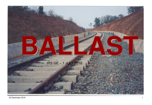
Ballast cleaning machine. Ballast gets pulverized due to hammering action of passing loads raising the level of fines in the ballast.

E N D
Ballast cleaning machine • Ballast gets pulverized due to hammering action of passing loads raising the level of fines in the ballast. • Sand and dust gets mixed up due to vagaries of weather and materials falling down from freight wagons, keep on contaminating the ballast, its load distribution angle reduces, diminishing its load dispersing function, ballast looses elasticity causing rapid deterioration of track geometry.
Ballast cleaning machine contd.. Due to presence of bad formation, ballast attrition, excessive rainfall and dropping of ashes and ore, ballast gets choked up and track drainage is impaired. in such situation it becomes necessary to screen the ballast right up to the formation level/sub ballast level. Deep screening should be carried out in the following situations by providing full ballast cushion :-
Ballast cleaning machine contd.. Prior to CTR Prior to TSR Where the caking of ballast has resulted in unsatisfactory riding Before converting existing track, fish plated or SWR into LWR or CWR. The entire track must be deep screened at least once in 6-8 years.
Ballast cleaning machine contd. Therefore as a general principle, ballast cleaning become due when there is 25% pollution and necessary when it is more than 40%. For mechanized ballast cleaning, various types of machines are available in world market. Indian railways have procured the following machines from M/s Plasser & Theurer Austria.
Ballast cleaning machine contd. RM–80 for plain track cap. 650 m3/hr, over all length 31800 mm , width 3150mm, weight 91 tonne, powered by two engines Deutz make, 333 KW each. Rm-76 for plain track as well as point and crossing cap 550m3/hr. Approx. Overall length 24690, width 3100, weight 69 tonne, powered by 219 Kw engine. Frm-80 for shoulder ballast cleaning, output 550m3/hr. Approx. overall length 39190, width 3100 mm, total weight 80 t , engine 348 kw.
Principle of ballast cleaning machine When a guided endless chain with cutting tools is passed under the bottom of sleeper with speed, it cuts caked up ballast and muck and carry it away along with it to a set of vibrating screens for cleaning. Muck is thrown out through conveyors and cleaned ballast is put back in track. In this process machine also moves forward as the work progresses. Due to paucity of space, salient features of rm-80 are discussed here, which constitute the largest numbers on Indian railways.
Main units Excavation unit Screening unit Conveyor system for distribution of ballast and waste disposal Track lifting & slewing unit Engines
Parts of excavation unit • Main link 82 nos. • Intermediate link 82 • Chain bolt 2 in each link • Special headed bolt with double nut and 1 per chain bolt One spring washer • Chain fingers 5 per link • Lock washer & fixing pin 5 per link • Corner rollers 5 nos • Turret gear 1 no. • Chain guides/trough ascending 1no descending 1no
Parts of excavation unit contd. • Chain guides/ trough 1 no ascending & 1 no descending • Wear plates & wear strips Chain rotation 1. Hydraulic motor 335 hp 2. Turret gear speed 1.8 to 3.4 m/sec 3. Speed of turret 2.7 m/sec Gear normally adopted
Ballast movement in B C M OUT OF TRACK TRACK BALLAST + 80 MM MAIN WASTE MUCK SCREEN CONVEYOR CONVEYOR 50 MM SCREEN BALLAST 25 MM DISTB. SCREEN CONVEYOR
B C MContd. The chain becomes loose as it becomes old & ovality in pin holes develops. This can be tightened hydraulically. At the time of starting work a trench has to be dug between two sleepers, long enough(length of cutter bar 2.15m*1m*0.3m) to accommodate cutter bar and deep enough that top most portion of cutter bar is inserted from one side along with chain link in it. After each day of work the chain is disconnected near the ends of cutter bar and left at site. Next day work is started by joining the chain.
Maintenance of excavation chain Guide rollers, wear arcs, fingers , wear plates, wear strips, cutter bar, main & intermediate link, turret gear etc. Constitute fast wearing components. Adequate stocks of these parts must be maintained for uninterrupted working.
Screening unit It is a three grade screening unit with metal screen providing a total screening surface of 30 m2These screens are vibrated linearly with the help of eccentric masses. Originally the manufacturer had provided three types of screens viz 80mm on top, 50mm in the middle and 36mm at the bottom. Over sized material is dropped from top screen through chutes on the waste conveyer belt, for disposing off out side track.
Screening unit contd. Both sides of screening unit have adjustable out lets for depositing excess ballast to the desired side of the track. Screening unit can be kept level on super elevated track by operating concerned hydraulic cylinder. Keeping economics of operation in mind, the proposed size of ballast screens are 80mm,50mm and 30mm.
Conveyor system • There are four conveyors in BCM • Ballast distribution – 1 for left & 1 for right ( clean ballast). • Main conveyor – 1 no. For carrying waste up to spoil / waste conveyor. • Waste conveyor – 1 no. To carry spoil or waste ( it can be fixed left or right & can be folded and fastened when not in use and traveling)
Track lifting and slewing unit It is provided near excavation unit ,it can be lifted up to 25cms. And slewed up to ±30cms this is useful to decrease the cutting depth and to avoid obstacles like platform walls etc.
Engines Two engines are provided in BCM- Model no. Bf 12 l 513 c Make – DEUTZ Air cooled H.P. 453 of each engine @ 2300 rpm Firing order :- 1-8-5-10-3-7-6-11-2-9-4-12
Function of first engine Travel drive Work drive Op. of chain guides Ballast distributing conveyors LHS, RHS Operation of main conveyor Operation of waste conveyor Operation of clutch pump for drive axle 1&2 Cooling of main gear box (front) oil Chain guides (LHS, RHS) up & dn , left – right Chain tensioning cyl. , lifting device Additional cutter chain pump
Function of second engine Travel drive Work drive Chain drive Screen drive Op. Of clutch pump for drive axle 3&4 Cooling of main gear box (rear) oil
Attentions for working of BCM Frequent shifting of BCM is not conductive to good work and adequate progress. Adequate stock of cutter chains, wear plates and other fast wearing parts for uninterrupted working of BCM is must . A joint plan with operating dept. For a min. 2.5 - 3 hrs block everyday for working of BCM. Before work by BCM it is necessary to survey the section and decide about the proposed profile of track. For free running of cutter bar and to avoid cutting of formation a min. cushion of 250 -270 mm be ensured .
BCM Contd. No obstruction should lie in a width of 4100 mm (2050 mm on either side of centre of track) to avoid infringement to the cutter chain. In electrified sections foundation distance to be accurately measured to ensure free movement of chain. Permanent obstructions such as cables signaling rods etc. Be temporarily disconnected. Embedded rail pieces, tie-bars etc. Be removed in advance. On girder bridges the guard rail at approaches be removed in advance.
BCM Contd. • No obstruction should lie in a width of 4100 mm (2050 mm on either side of centre of track) to avoid infringement to the cutter chain. • In electrified sections foundation distance to be accurately measured to ensure free movement of chain. • Permanent obstructions such as cables signaling rods etc. be temporarily disconnected. • Embedded rail pieces, tie-bars etc. be removed in advance. • On girder bridges the guard rail at approaches be removed in advance.
BCMContd. In case of level X- ing it should be opened so as to enable the m/c to work. 100% fittings be intact so that no sleeper becomes loose and comes in the way of the cutter chain. A set of gas cutting m/c should be kept with the m/c. A trench of 30 cm depth and 1 m width should be made for setting of cutter bar and chain by removing one sleeper.
BCM Contd. • Utmost caution should be observed for waste conveyor to avoid hitting against electrical mast/signal post. Safety switch to sense the mast should be kept on. • All the staff should wear safety helmets and masks. • Screening should be stooped well before expiry of traffic block to permit proper closing of the work and packing before resumption of traffic. • One person on either should move with the m/c to watch any obstruction to cutter chain. • The vertical and lateral clearances for OHE, signal post etc. Should be checked adjusted before clearing of block.
BCMContd. Ballast recoupment activity should synchronize with deep screening activity so as to enable raising speed to normal after packing One round of tamping along with DTS should be carried out immediately after deep screening to resume traffic at a speed of 40 kmph. One watchman should be posted at the location where cutter bar chain are left.
BCMContd. Problems occur during working- excavation unit Any obstruction entangle with the chain Breakage of chain – bolt so chain becomes part Entanglement of wear plates with chain Chain fell down from turret Chain too loose Chain finger worn out Chain speed is not proper Hard bed or wet soil Motor for turret gear not working properly Cleaning is done without track lifting
Screening unit Vibration screen may be choked Screens should be of proper mesh size Reconditioning of screens shall be done Vibration of shaft is improper Screening unit is not in horizontal position Hood closed Flapper should be in centre position
Conveyor unit • Alignment of conveyor shall be proper • Conveyor rollers shall function properly • Belts run to one side throughout entire length • Belt not tight enough • Material built up on belts • Frozen idlers • Belts slip on starting • Belts improperly spliced • Material between belt pulley • Belts become brittle or crack due to abrasive, heat, oil, entanglement of tie bars etc. • Belt tear off to its full length • Puncturing of belt by ballast trapped bet. Roller and belt
Lifting unit Lifting not take place due to no pressure Up position switch is defective Clamping pressure is not sufficient Worn out rollers