Download
1 / 20
210 likes | 514 Views
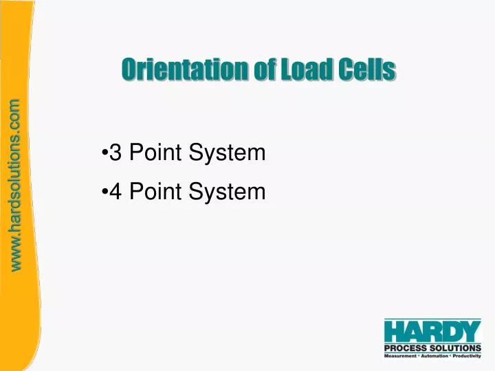
Orientation of Load Cells. 3 Point System 4 Point System. Types of Load Points. There are three models of load cells that work in concert to help provide a bind free weighing system. FIXED: Provides a pivot point that prevents the scale from moving left or right and allowing a 360 degree

E N D
Orientation of Load Cells 3 Point System 4 Point System
Types of Load Points • There are three models of load cells that work in concert to help provide a bind free weighing system. • FIXED: Provides a pivot point that prevents the scale • from moving left or right and allowing a 360 degree • radius. • BUMPER: Works with the FIXED mount to limit the • 360 degree rotation, and allow expansion. • Orientation is very important. • SLIDER: Completes the trio and is used to support the remaining vessel leg(s). The SLIDER allows expansion in any direction and limited by the other mount types. NOTE: There is additional installation information in the load point manuals
X X The Fixed MountingAssembly Fixed • FIXED: Provides a pivot point that prevents the scale from moving left or right and allowing a 360 degree radius. • Limits right, left and forward, back scale movements • Provides a certain amount of vessel checking • A bolt in the front of the load point mount provides lift off protection. • Position load points to protect the cabling from traffic, mechanical pinch points and any possible damage.
Steel Blocks limit the movement Left and Right. Bumper The Bumper Mounting Assembly Designed to allow movement forward and aft to compensate for vessel expansion and contraction. • BUMPER: Works with the FIXED mount to limit the 360 degree rotation, and allow expansion. • Correct orientation for this load point is very important. • The cable end must point directly at or directly away from the FIXED load point. • This acts as a limited check system to vessel movement. • An incorrect mount alignment could allow the vessel • to slip off the load point assemblies.
Slider The Slider Mounting Assembly • SLIDER: Completes the trio and is used to support the remaining vessel legs. The SLIDER allows expansion in any direction and is only limited by the FIXED and BUMPER mounts and piping. • The Slider Load point can be orientated in any direction. • Position load points to protect the cabling from traffic, mechanical pinch points and any possible damage.
3 Point System • One Fixed Point Load Point • One Bumper Load Point • One Slider Load Point
4 Point System • One Fixed Point Load Point • One Bumper Load Point • Two Slider Load Points
RULES OF ORIENTATION • Fixed load cell • No rules of orientation • Bumper load cell • Lengthwise axis must be within 45o towards fixed load cell • Slider load cell • No rules of orientation
ACCEPTABLE ORIENTATION BUMPER load point must follow the rules of association to the Fixed load point. FIXED load point can be in any orientation SLIDER load point can be in any orientation
ACCEPTABLE ORIENTATION Equally spaced at 120 degree around the vessel. The same concerns and orientation problems and solutions are equally appropriate for a round vessel with four load points. The difference is the 4 point vessel will be equally spaced 90 degrees around the vessel. BUMPER FIXED SLIDER
ACCEPTABLE ORIENTATION Equally spaced at 120 degree around the vessel. The orientation makes two locations crowded, pinch point, or traffic. You can move the bumper mount to an open area and re- orientate the fixed and slider load point to avoid the problem. BUMPER FIXED SLIDER
>45o INCORRECT ORIENTATION BUMPER FIXED SLIDER Rotation can allow the vessel to twist off the load points.
ACCEPTABLE ORIENTATION Equally spaced at 90 degrees around the vessel. the same concerns and orientation problems and solutions are equally appropriate for a round or square vessels with four or three load points. The difference is the 4 point vessel will be equally spaced 90 degrees around the vessel. SLIDER FIXED BUMPER SLIDER
ACCEPTABLE ORIENTATION Equally spaced at 90 degree around the vessel. The orientation makes locations crowded by pinch point, or traffic. You can move the bumper mount to an open area and re-orientate the fixed and slider load points to avoid the problem. SLIDER FIXED BUMPER SLIDER
ACCEPTABLE ORIENTATION Positioned on the longest side BUMPER FIXED SLIDER SLIDER The same concerns and orientation problems and solutions are equally appropriate for a round vessel with four load points. The difference is the 4 point vessel will be equally spaced 90 degrees around the vessel.
CORRECT ORIENTATION BUMPER FIXED BUMPER FIXED For conveyor systems you can use this combination to help stabilize the belt and flow alignment. You have minimized side motion and allowed expansion with the length of the scale.
>45o INCORRECT ORIENTATION FIXED SLIDER SLIDER BUMPER This would allow to much horizontal movement and could allow the load point to fall off the mount.
S S F B F B S S Acceptable Orientations Both orientations will work. Both of these orientation will work and are recommended methods. The top orientation will not work if this is a long rectangular scale with too long of angles. Install the Fixed and Bumper mounts together on the longest side. The bottom example is the preferred.
B F This orientation will not work. S Rotation will allow the vessel to fall off the mount. S
Any Questions? There is additional installation information in the load point manuals. We tried to show several scales with typical load point installations, but we cannot cover all combinations. Please contact Hardy Instruments Technical Support for any additional question. 858-278-2900 ext 1757