Download
1 / 48
480 likes | 543 Views
Internetworking: addressing, forwarding, resolution, fragmentation. Shivkumar Kalyanaraman Rensselaer Polytechnic Institute shivkuma@ecse.rpi.edu http://www.ecse.rpi.edu/Homepages/shivkuma Based in part upon the slides of Prof. Raj Jain

E N D
Internetworking: addressing, forwarding, resolution, fragmentation Shivkumar Kalyanaraman Rensselaer Polytechnic Institute shivkuma@ecse.rpi.edu http://www.ecse.rpi.edu/Homepages/shivkuma Based in part upon the slides of Prof. Raj Jain (OSU), S. Keshav (Cornell), L. Peterson (Arizona)
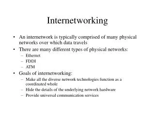
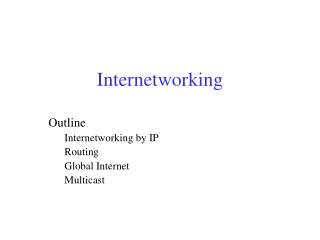
Internetworking: heterogeneity & scale • IP solution: • Provide new packet format and overlay it on subnets. • Implications: Hierarchical address, address resolution, fragmentation/re-assembly, packet format design, forwarding algorithm etc • Protocols: IP and ARP Overview
The Internetworking Problem • Two nodes communicating across a “network of networks”… How to transport packets through this heterogeneous mass ? • Problems: heterogeneity and scaling • Heterogeneity: • How to interconnect a large number of disparate networks ? (lower layers) • How to support a wide variety of applications ? (upper layers) A B
The Internetworking Problem • Scaling: • How to support a large number of end-nodes and applications in this interconnected network ? • Possible solutions: • Translation (eg: bridges): specify a separate mapping between every pair of protocols • (+) No software changes in networks required. • (-) Need to specify N mappings when a new lower layer protocol is added to the list • (-) When many networks, subset = 0 • (-) Mapping may be asymmetric • Overlay model: Define a new protocol (IP) and map all networks to IP
The Internetworking Problem • (+) Require only one mapping (IP -> new protocol) when a new protocol is added • (+) Global address space can be created for universal addressibility/scaling • (-) Requires some changes in lower networks (eg: protocol type field for IP) • (-) IP has to be necessarily simple else mapping will be hard. • Even in its current form mapping IP to ATM has proven to be really hard. • Basis for “best-effort” forwarding • (-) Mapping infrastructure needed: address hierarchy, address resolution, fragmentation
Internet’s Architectural principles • End-to-end principle: (Dave Clark, MIT) • Network provides minimum functionality (connectionless forwarding, routing) • Value-added functions at hosts (control functions): opposite of telephony model (phone simple, network complex) • Idea originated in security: trust the network or the end-systems (what’s finally received) ? • Beat the X.25 approach: stateful, connection-oriented, hop-by-hop control.
Architectural principles (contd) • IP over everything: (Vint Cerf, VP, MCI) • An internetworking protocol which works over all underlying sub-networks and provides a single, simple service model (“best-effort delivery”) to the user.
Architectural Principles (Contd) • Connectivity is its own reward: • The more the users of the Internet, the more valuable it is (Metcalfe’s law) • Pragmatic design: • Support all platforms, all kinds of users. • “Understand/receive as many formats as possible; send using a standard format” • Build de facto standards: requires rough consensus and running code. Anyone can participate in standardization.
History (1960s) • 1961: The first paper on packet switching by Leonard Kleinrock, UCLA. • 1962: ARPA computer program begins … • 1965: First actual network experiment, Lincoln Labs (now part of MIT) TX-2 tied to SDC's Q32 by Larry Roberts. • 1966-67: ARPAnet program begins • 1968: Bob Karn’s team atBBN builds first Interface Message Processor (IMP) later known as a “router”.
History (1970s) • 1969:First RFC written • 1970: ARPAnet spans US (total: ~10 nodes) • 1972: Email, ftp born (due to Dave Crocker ) • 1973:Bob Metcalfe at Xerox designs Ethernet • 1974: Vint Cerf& Kahnbuild first version of TCP, ARPAnet routing is revised • 1977-78: TCP split into TCP and IP • 1980-83:ARPAnet splits into ARPAnet and MILNET, and offers software at low cost to universities. NSF invests in CSNET connecting computer science departments.
History (1980-90s) • 1983:UC Berkeley and BBN integrate TCP/IP into UNIX 4.2 BSD. Berkeley develops network utilities and sockets API. • 1985-87: Decentralization of naming & addressing. NSF lets regional networks to connect to ARPAnet via a backbone, NSFnet. • 1987-90: Companies join Internet. EBONE (Europe) connected to NSFnet. TCP improved to handle congestion by Van Jacobson. • 1990-93:Steve Deering pioneers multicast and IPv6 work in IETF. Marc Andresson writes the first Mosaic browser.
The 1990s • 1993-present:Internet still grows exponentially. NSFnet is privatized. ATM networks promise new future for backbones. Internet access through telephones, cable, television, and electric companies. ISPs, E-commerce, security, real-time services are the talk of the town. Cisco stock grows 100-fold.
Internet = Virtual Network • Any computer can talk to any other computer Net 2 Net 3 Net 1 Net 4 Fig 13.3
How does IP forwarding work ? • A) Source & Destination in same network (fig 3.3 in text) • Recognize that destination IP address is on same network. [1] • Find the destination LAN address. [2] • Send IP packet encapsulated in LAN frame directly to the destination LAN address. • Encapsulation => source/destination IP addresses don’t change
IP forwarding (contd) • B) Source & Destination in different networks (fig 3.4 in text) • Recognize that destination IP address is not on same network. [1] • Look up destination IP address in a (routing) table to find a match, called the next hop router IP address. • Send packet encapsulated in a LAN frame to the LAN address corresponding to the IP address of the next-hop router. [2]
Addressing & Resolution • [1] How to find if destination is in the same network ? • IP address = network ID + host ID. Source and destination network IDs match => same network • Splitting address into multiple parts is called hierarchical addressing • [2]: How to find the LAN address corresponding to an IP address ? • Address Resolution Problem. • Solution: ARP, RARP (next chapter)
Net 1 Forward to R1 Net 2 Deliver Direct Net 3 Deliver Direct Net 4 Forward to R3 Route Table Lookup • Intermediate routers lookup the destination network-ID • Deliver datagrams to next-hop and finally to destination network, not to host directly • Hierarchical forwarding: routing tables scale. Net 1 Net 2 Net 3 Net 4 R1 R2 R3 Destination Next Hop Table at R2:
IP Address Formats • Class A: 0 Network Host 1 7 24 bits • Class B: 10 Network Host 2 14 16 bits • Class C: 110 Network Host 3 21 8 bits • Class D: 1110 Multicast Group addresses 4 28 bits • Class E: Reserved. Router Router
Dotted Decimal Notation • Binary: 11000000 00000101 00110000 00000011Hex Colon: C0:05:30:03 Dotted Decimal: 192.5.48.3 Class Range A 0 through 127 B 128 through 191 C 192 through 223 D 224 through 239 E 240 through 255
An Addressing Example Router • All hosts on a network have the same network prefix (I.e. network ID) 128.10 128.211 Router 128.10.0.1 128.10.0.2 128.211.6.115 10.0.0.37 10.0.0.49 192.5.48.3 10 Router 192.5.48
Some special IP addresses • All-0s This computer • All-1s All hosts on this net (limited broadcast: don’t forward out of this net) • All-0 host suffix Network Address (‘0’ means ‘this’) • All-1 host suffix All hosts on the destination net (directed broadcast). • 127.*.*.* Loopback through IP layer • Further classification in fig 3.9 of text
Subnet Addressing • Classful addressing inefficient: Everyone wants class B addresses • Can we split class A, B addresses spaces and accommodate more networks ? • Need another level of hierarchy. Defined by “subnet mask”, which is general specifies the sets of bits belonging to the network address and host address respectively • External routers send to “network” specified by the “network ID” and have smaller routing tables Network Host Boundary is flexible, and defined by subnet mask
Subnet Addressing (Contd) • Internal routers & hosts use subnet mask to identify “subnet ID” and route packets between “subnets” within the “network”. • Eg: Mask: 255.255.255.0 => subnet ID = 8 bits with upto 62 hosts/subnet • Route table lookup: • IF ((Mask[i] & Destination Addr) = = Destination[i]) Forward to NextHop[i] • Subnet mask can end on any bit. • Mask must have contiguous 1s followed by contiguous zeros. Routers do not support other types of masks.
Destination Mask Next Hop 30.0.0.0 255.0.0.0 40.0.0.7 40.0.0.0 255.0.0.0 Deliver direct 128.1.0.0 255.255.0.0 Deliver direct 192.4.10.0 255.255.255.0 128.1.0.9 Route Table Lookup: Example 30.0.0.7 40.0.0.8 128.1.0.9 40.0.0.0 30.0.0.0 128.1.0.0 192.4.0.0 40.0.0.7 128.1.0.8 192.4.10.9
Variable Length Subnet Mask (VLSM) • Basic subneting: refers to a fixed mask in addition to natural mask (i.e. class A, B etc). • I.e. only a single mask (eg:: 255.255.255.0) can be used for all networks covered by the natural mask. • VLSM: Multiple different masks possible in a single class address space. • Eg: 255.255.255.0 and 255.255.254.0 could be used to subnet a single class B address space. • Allows more efficient use of address space.
Summary • Addressing: • Unique IP address per interface • Classful (A,B,C) => address allocation not efficient • Hierarchical => smaller routing tables • Provision for broadcast, multicast, loopback addresses • Subnet masks allow “subnets” within a “network” => improved address allocation efficiency • Forwarding: • Simple “next-hop” forwarding. • Last hop forwards directly to destination • Best-effort delivery : No error reporting. Delay, out-of-order, corruption, and loss possible => problem of higher layers! • Forwarding vs routing: tables setup by separate algorithm (s)
IP Features • Connectionless service • Addressing • Data forwarding • Fragmentation and reassembly • Supports variable size datagrams • Best-effort delivery: Delay, out-of-order, corruption, and loss possible. Higher layers should handle these. • Provides only “Send” and “Delivery” servicesError and control messages generated by Internet Control Message Protocol (ICMP)
What IP does NOT provide • End-to-end data reliability & flow control (done by TCP or application layer protocols) • Sequencing of packets (like TCP) • Error detection in payload (TCP, UDP or other transport layers) • Error reporting (ICMP) • Setting up route tables (RIP, OSPF, BGP etc) • Connection setup (it is connectionless) • Address/Name resolution (ARP, RARP, DNS) • Configuration (BOOTP, DHCP) • Multicast (IGMP, MBONE)
Vers H Len TOS Total Length Identification Flags Fragment Offset Time to live Protocol Header Checksum Source IP Address Destination IP Address IP Options (if any) Padding Data IP Datagram Format 0 4 8 16 32
IP Datagram Format • First Word purpose: info, variable size header & packet. • Version (4 bits) • Internet header length (4 bits): units of 32-bit words. Min header is 5 words or 20 bytes. • Type of service (TOS: 8 bits): Reliability, precedence, delay, and throughput. Not widely supported • Total length (16 bits): header + data. Units of bytes. Total must be less than 64 kB.
IP Header (Cont) • 2nd Word Purpose: fragmentation • Identifier (16 bits): Helps uniquely identify the datagram between any source, destination address • Flags (3 bits): More Flag (MF):more fragments Don’t Fragment (DF) Reserved • Fragment offset (13 bits): In units of 8 bytes
IP Header (Cont) • Third word purpose: demuxing, error/looping control, timeout. • Time to live (8 bits): Specified in router hops • Protocol (8 bits): Next level protocol to receive the data: for de-multiplexing. • Header checksum (16 bits): 1’s complement sum of all 16-bit words in the header. • Change header => modify checksum using 1’s complement arithmetic. • Source Address (32 bits): Original source. Does not change along the path.
Header Format (contd) • Destination Address (32 bits): Final destination. Does not change along the path. • Options (variable length): Security, source route, record route, stream id (used for voice) for reserved resources, timestamp recording • Padding (variable length): Makes header length a multiple of 4 • Payload Data (variable length): Data + header < 65,535 bytes
Maximum Transmission Unit • Each subnet has a maximum frame sizeEthernet: 1518 bytesFDDI: 4500 bytesToken Ring: 2 to 4 kB • Transmission Unit = IP datagram (data + header) • Each subnet has a maximum IP datagram length (header + payload) = MTU Net 1MTU=1500 Net 2MTU=1000 R R S
Fragmentation • Datagrams larger than MTU are fragmented • Original header is copied to each fragment and then modified (fragment flag, fragment offset, length,...) • Some option fields are copied (see RFC 791) IP Header Original Datagram IP Hdr 1 Data 1 IP Hdr 2 Data 2 IP Hdr 3 Data 3
Fragmentation Example MTU = 1500B MTU = 280B IHL=5, ID = 111, More = 1 Offset = 0W, Len = 276B IHL = 5, ID = 111, More = 0 Offset = 0W, Len = 472B IHL=5, ID = 111, More = 0 Offset = 32W, Len = 216B • Payload size 452 bytes needs to be transmitted across a Ethernet (MTU=1500B) and a SLIP line (MTU=280B) • Length = 472B, Header = 20B => Payload = 452B • Fragments need to be multiple of 8-bytes. • Nearest multiple to 260 (280 -20B) is 256B • First fragment length = 256B + 20B = 276B. • Second fragment length = (452B- 256B) + 20B = 216B
Reassembly • Reassembly only at the final destination • Partial datagrams are discarded after a timeout • Fragments can be further fragmented along the path. Subfragments have a format similar to fragments. • Minimum MTU along a path Path MTU S D Net 2MTU=1000 Net 1MTU=1500 Net 3MTU=1500 R1 R2
Further notes on Fragmentation • Performance: single fragment lost => entire packet useless. Waste of resources all along the way. Ref: Kent & Mogul, 1987 • Don’t Fragment (DF) bit set => datagram discarded if need to fragment. ICMP message generated: may specify MTU (default = 0) • Used to determine Path MTU (in TCP & UDP) • The transport and application layer headers do not appear in all fragments. Problem if you need to peep into those headers.
Discussion on IP Header Design • If fragmentation is going to be avoided all the time, why not have the 4-bytes of fragmentation info as an IP option ? • Is 32-bit addresses going to be enough ? • Why mess with variable length headers ? Can the variability in header length be controlled to allow better encoding ? • Are the IP options really that useful ? Why variable length option headers ? • Many of these issues addressed in IPv6.
Resolution Problems and Solutions • Indirection through addressing/naming => requires resolution • Problem usually is to map destination layer N address to its layer N-1 address to allow packet transmission in layer N-1. • 1. Direct mapping: Make the physical addresses equal to the host ID part. • Mapping is easy. • Only possible if admin has power to choose both IP and physical address. • Ethernet addresses come preassigned (so do part of IP addresses!). • Ethernet addresses are 48 bits vs IP addresses which are 32-bits.
ARP techniques (contd) • 2: Table Lookup:Searching or indexing to get MAC addresses • Similar to lookup in /etc/hosts for names • Problem: change Ethernet card => change table IP Address MAC Address 197.15.3.1 0A:4B:00:00:07:08 197.15.3.2 0B:4B:00:00:07:00 197.15.3.3 0A:5B:00:01:01:03
ARP techniques (Cont) • 3. Dynamic Binding: ARP • The host broadcasts a request: “What is the MAC address of 127.123.115.08?” • The host whose IP address is 127.123.115.08 replies back: “The MAC address for 127.123.115.08 is 8A-5F-3C-23-45-5616” • All three methods are allowed in TCP/IP networks.
ARP Message Format 0 8 16 24 32 • Type: ARP handles many layer 3 and layer 2s • Protocol Address type: 0x0800 = IP • Operation: 1= Request, 2=Response • ARP messages are sent directly to MAC layer H/W Address Type Protocol Address Type H/W Adr Len Prot Adr Len Operation Sender’s h/w address (6 bytes) Sender’s Prot Address (4 bytes) Target h/w address (6 bytes) Target Protocol Address (4 bytes)
ARP Processing • See ARP dynamics in figs 4.2, 4.4, 4.5 • ARP responses are cached. Replacement: • Cache table fills up => LRU policy used • Timeout: e.g., 20 minutes • Others may snoop on ARP, IP packets for address bindings • Note: • A point-to-point link like SLIP does not require ARP. • Telephony does not require ARP.
Reverse ARP (RARP) • H/w (MAC) address -> IP address • Used by diskless systems • RARP server responds. • Once IP address is obtained, use “tftp” to get a boot image. Extra transaction! • RARP design complex: • RARP request broadcast, not unicast! • RARP server is a user process and maintains table for multiple hosts (/etc/ethers). Contrast: no ARP server
RARP (contd) • RARP cannot use IP • Needs to set unique Ethernet frame type (0x8035) • Works through a filter like BPF or nit_if/nit_pf streams modules (fig: A.1, A.2) • Multiple RARP servers needed for reliability • RARP servers cannot be consolidated since RARP requests are broadcasts => router cannot forward • BOOTP, DHCP replaces RARP
Discussion & Informal Exercises • ARP, RARP, BOOTP, DHCP solve parts of the autoconfiguration (plug-and-play) problem. • We will re-examine autoconfiguration later … • Exercises: • Read the man page for the “arp” command • Approximate the tcpdump experiments given in the text using your rcs and networks lab accounts. • ARP requires a broadcast enabled LAN. What would happen on a non-broadcast medium access (NBMA) LAN ? Guess first and then see RFC 1735.
Summary • Internet architectural principles • IP header: supports connectionless delivery, variable length pkts/headers/options, fragmentation/reassembly, • Fragmentation/Reassembly, Path MTU discovery. • ARP, RARP: address mapping • Additional reading: Addressing101 (on course web page)