Download
1 / 15
170 likes | 374 Views
Loran-C P-Static. Presented to: Loran Integrity Protection Panel Meeting July 24-25, 2002, Stanford University David W. Diggle, Frank van Graas. OVERVIEW. Precipitation Static (P-Static) Two main mechanisms affecting Loran-C Loop versus wire antennas Loop antenna design/feasibility

E N D
Loran-C P-Static Presented to: Loran Integrity Protection Panel Meeting July 24-25, 2002, Stanford University David W. Diggle, Frank van Graas
OVERVIEW • Precipitation Static (P-Static) • Two main mechanisms affecting Loran-C • Loop versus wire antennas • Loop antenna design/feasibility • Conclusions & Recommendations
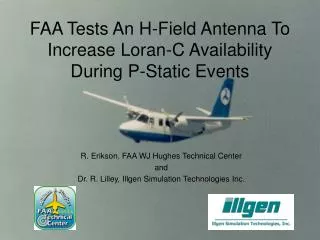
Precipitation Static (P-Static) • Charge build-up may be caused by: • Charged rain droplets • Dry air or snow • Wing-tips in different potentials (clouds, lightning) • Potentials can easily reach 100 kV. • Charge build-up causes pulsed discharges at a rate of 1 to 1000 discharges per second. • Most aircraft have static dischargers installed on trailing edges to slowly discharge the aircraft.
P-Static and Loran-C Receivers • Two main mechanisms • Charging of antenna relative to the fuselage • Wire (E-Field) antenna has a high impedance and cannot be terminated to absorb charges (continuous termination would also terminate the Loran signal) • Loop (H-Field) antenna has a very low impedance (also a low profile) • “Popping” discharge of aircraft to surrounding air • Affects both wire and loop antennas • Older wire antenna pre-amps could saturate due to “ringing” in the pre-amp circuitry
Loran-C Wire versus Loop Antennas • Large effective height • Little voltage amplification needed • High impedance (MW) • Charge build-up (cannot be terminated) • Antenna phase pattern is omnidirectional • Whip or wire antenna Wire (E-Field) Loop (H-Field) • Small effective height • Large voltage amplification needed (low noise pre-amp) • Low impedance (10W) • No charge build-up (antenna is grounded) • One loop creates 0 and 180 degrees. • Conformal antenna
Wire P-Static Problem Antenna is short relative to the Loran-C wavelength (3000 m): - High impedance (MW)- Pre-amp must have a high input impedance Voltage too high due to charge build-up: Neon bulb conduct and shorts-out the Loran signal
Loop Antennas for Loran-C • Main Advantage for Aviation: Low sensitivity to P-Static due to antenna charge build-up (which causes degraded navigation or loss-of-navigation) • Perceived Issues: • Phase Pattern is not Omnidirectional • Combine two loops in phase-quadrature and correct for the antenna phase using the known, relative angle of arrival; or • Process signals from two loops separately • Signal-to-Noise Ratio • Small effective antenna height necessitates an ultra low-noise pre-amplifier (or a large antenna)
Block of Ferrite Loop 2 Loop 1 Loop Antenna Loop 1 Loop 2 90o
Phase-Quadrature • Loops 1 and 2 are combined in phase-quadrature to obtain an omnidirectional antenna pattern • Received phaseis a function ofthe direction ofsignal arrival • Useful forreception ofLoran Comm.signals (phaseoffset does notaffect decoding) 0o Loop 2 270o 90o Loop 1 180o Horizontal Antenna Pattern
Phase Correction Master X Secondary a Approximate UserLocation Time Difference M-X: Correction =
Loop Antenna System Design • Effective Height: 1.5 mm (300 mm for E-Field) • Need 200 times more voltage amplification • SNR (in dB) = Loran (dB/mV/m) - Noise (dB/mV/m) • Loran Signal at 300 nmi: 60 dB/mV/m • Atmospheric Noise (avg.): 45 dB/mV/m • At Ohio Univ., Seneca (M) SNR 15 dB • Input Noise Voltage • Should be below Atmospheric Noise at the antenna output: 0.25 mV
Ultra Low-Noise Amplifier • Good Amplifier (MAX 410) input noiseThus, et 0.5 mV • This is the amplifier noise at the output of the impedance transformer 1:25 (Voltage 1:5). • Therefore, amplifier noise referred to the input of the transformer is 0.1 mV • Provides 8 dB of margin relative to 0.25 mV
Antennas Wire (E-Field) II Morrow A-16 Loop (H-Field) King Radio KA42A
Conclusions & Recommendations • Conclusions • Loop antenna reduces the Loran-C P-Static problem • Conformal Loran-C antenna exists on all aircraft (use TSO’d ADF antenna) • Ultra Low-Noise pre-amplifier is feasible for Loran-C loop antenna. • Recommendations for further work • Detailed investigation into P-Static environment (RF Data Collection) • Develop circuitry to enable dual-use ADF/Loran of a single ADF loop antenna