Download
1 / 33
350 likes | 543 Views
DC Brushed Motors & Power Transmission. 2014 FRC. Ken Stafford. Permanent Magnet Brushed?. Stator (Field) made of permanent magnets Rotor (Armature) made with wire coils (electromagnets) Commutator has brushes to pass current. The Basics…. Imperfect Transducers

E N D
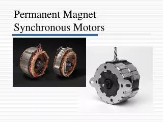
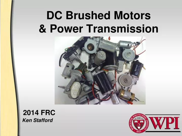
DC Brushed Motors& Power Transmission 2014 FRC Ken Stafford
Permanent Magnet Brushed? • Stator (Field) made of permanent magnets • Rotor (Armature) made with wire coils (electromagnets) • Commutatorhas brushes to pass current
The Basics… • Imperfect Transducers • Electrical Power to Mechanical Power • Electrical Power to Thermal Power! • Electrical Power (input) • Volts times Amps (Watts) • EG: CIM @ 40A has 480W input @12V • Mechanical Power (output) • Work divided by Time or • RPM times Torque (Watts or Hp) • EG: CIM (40A/12V) 3800rpm/6.15 inlbs=275W
The more basic Basics… • Torque “twisting effort” • EG: shaft turning, force at the end of an arm, force at the circumference of wheel… “pushing/pulling strength” • Unlimited torque available through any motor with appropriate transmission • Power “rate of doing work” • EG: speed of lifting, torque times rpm, force times velocity… “robot/mechanism speed” • Maximum is set by motor design—only decreases through transmission
Manufacturers provide varying data Not too difficult to obtain experimentally with basic lab equipment You need only four values to predict ideal performance At full speed (no load) Motor Speed (rpm) Current (Amps) At maximum torque (stall) Torque (inlbs) Current (Amps) Motor Parameters
Example: Taigene (Van Door) • Motor clamped in vise hooked to calibrated power supply • Free-running rpm by timed counting • Stall torque by linear force balance at end of measured arm • Current measured directly from power supply • Results: • Free running: 47.5 rpm @ 1.23 A • Stall: 360 in lbs @ 24.2 A
Performance Map Note: This is at full rated voltage
So…what does this mean? • Max Torque occurs at zero rpm (stall) • Also produces zero Mech Power and Max Thermal Power • Lightweight, air-cooled motors will smoke in seconds
More on Motors… • Max Power occurs at 50% Stall Torque, ~ 50% Stall Current, and 50% Free-running speed • Any sub-maximum power is available at 2 different operating conditions • High speed/low torque • Low speed/high torque • Max Efficiency occurs at ~25% Stall Torque or ~60% Max Power
Typical FRC Motors • Sealed vsFan-Cooled • Thermal Protection • Anti-backdrivevsbackdrive resistant • Built in transmissions
Motor Selection Criterion • Power Requirement • Weight of Motor & Transmission • Physical Size of Motor & Transmission • Backdrive Characteristics • Continuous vs Intermittent Operations • Efficiency • Availability
Specific Recommendations • Sealed motors (eg CIM) • High torque, can handle intermittent high loads • Heavy • Application: • Driveline or other high power accessories • Must be kept LOW in chassis
Recommendations Cont. • Fan-cooled motors (eg FP) • Very high power/low weight/ intolerant of high load • Applications: • Shooters/fans
Recommendation Cont. • Worm Gear Motors (eg Van Door) • Thermal protection, backdrive resistant, low power, heavy • Applications: • Arm shoulder, turret • Low in chassis
Design Example • Build a winch to lift a 100 lbrobot 3 ft in 10 secs: • Mech Power = Work/Time * Conversion • Required Power = ((100 lb)(3 ft)/10 sec)(746 W/550 ft-lb/sec) = 40W • 12 of the 20 allowed 2014 FRC motors > 40W
Design Example (cont) • From the Performance Map • It produces 40 W at either 100 or 275 in-lb • At 100 in-lbs it’s ~45% efficient; at 275, it’s ~18%! • Design your drum radius so it develops 50 lbs of force with 100 in-lbs of torque • Radius = 100in-lbs/100 lbs = 1 in 100 lbs 2 in 100 in-lbs
Design Details Cont. • If holding a lifter/arm in position is important do not rely upon motor torque (overheating) • Previous example: ~30W to hold @ 1.0 in drum; ~180W to hold @ 2.75 in drum! • Design a mechanical one-way clutch/ • retractable ratchet or balance mechanism
Transmission Essentials • Unless you are VERY lucky…you will need ‘em • Transmissions can: 1) Modify output speed/torque. 2) Change direction of rotation 3) Physically separate motor from device • They will ALWAYS 4) Reduce power through losses
Transmission Essentials • Unless you are VERY lucky…you will need ‘em • Transmissions can: 1) Modify output speed and torque 2) Change direction of rotation 3) Physically separate motor from device • They will ALWAYS 4) Reduce power through losses
More Basics • For spur gears and chain/sprockets, it’s all about the number of teeth! • “Gear Train”, aka “Speed Ratio” e = Product of Drivers / Product of Driven = Speed out / Speed in = (Torque in / Torque out) * Sys efficiency
Speed Example • Driving elements: • 16 T gear • 18 T sprocket • Driven elements: • 54 T gear • 28 T sprocket • e = (16 * 18)/(54 * 28) = .19 • With motor @ 5000 rpm Roller speed = 5000 *.19 = 950 rpm
Torque Example • Same transmission: e =.19 • Losses occur at each “stage” • Typically 5% loss (η = .95) • You calculate you need 20 lbs force at the 2 inch dia roller Torque out = 20 lbs * 1 in = 20inlb Torque in = (.19 * 20 inlb) / (.95 * .95) = 4.2 inlb • Note: this would result in a 28 A load with the small CIM as shown
“Roller” Chain and Sprockets • Parameters (ANSI) • Chain Number: • 1st digit = pitch in 1/8 inches • 2nd digit = “roller” (0), “lightweight” (1), or “bushed” (5) • EG: #25: ¼ inch pitch without rollers, #35: 3/8 inch pitch without rollers • Strength (breaking/working): • #25 = 875/140 lbs • #35 = 2100/480 lbs • “Working” implies industrial duty/life expectancy
Chain Design Details • Sprocket sizes • Recommend 12T to 75T • Smaller causes vibration & excess wear • Larger leads to chain loss • Chain Wrap • 120 degree minimum for any drive or driven sprocket • Change routing, add idlers if necessary • Design in adjusters for long runs • Adjustment range should ideally be 2 pitch lengths (to avoid half-links)
Gears, gears, gears! • Parameters (ANSI) • (Diametral) Pitch: P = Number of Teeth/ Pitch Diameter • Integer number, normally divisible by 4 • EG: 32, 28, 24, 20, etc • Larger the P, the smaller/weaker the teeth • Pressure Angle: the actual off-tangent angle force transmission • Typically 14.5 or 20 degrees • 14.5 degrees weaker, more efficient
Spur Gear Design Details • Gear sizes • Recommend 12T to Infinity! (rack) • Smaller (“pinions”) are weak from under-cutting—esp 14.5 degree PA • All gears with same P and PA will fit • Transmission axle separation • An exact, easily computed distance D = (Total number of teeth/P) / 2 • EG: 16T & 42T, 24 Pitch gears D = ((16 + 42) / 24) / 2 = 1.208 inches • Can be 95-98% efficient/stage 16T 42T
Other Gear Stuff 50T • Worm Gears • Antibackdrive (Helix angle dependent, Window--yes; Van Door--no) • Woefully inefficient: η = .25-.75 • Very compact e = Number leads on worm / Teeth on Worm Gear = 4 / 50 = .08 • DO NOT USE FOR HI-POWER • Requires VERY secure bearing support 4
General Suggestions • Operate motors on left side of perf map • Air-cooled motors cannot operate near stall for more than a few seconds • Control top speed of operation by suitable gearing not by reduced voltage • Avoid powered anti-backdrive • Driveline ROT: no wheel-spin when blocked? = TOO HIGH GEARED!
Overall Caveats • Real world motors in robots will not operate at the peak values predicted on the performance maps • Batteries will sag, voltage will be lost through conductors, etc • You need to consider mechanical transmission efficiency when calculating motor requirements • Be careful to note reference voltage in manufacture’s data—automotive use 10.5V commonly