Download

1 / 14
150 likes | 298 Views
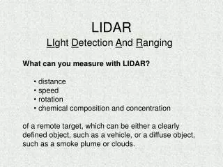
Nodding LIDAR. For Applied Research Associates By Roscoe Kane and John Barton. Background. LIDAR stands for Li ght D etection A nd R anging Emits a pulsed laser beam and measures the time between emission and return to determine distance

E N D
Nodding LIDAR For Applied Research Associates By Roscoe Kane and John Barton
Background • LIDAR stands for Light Detection And Ranging • Emits a pulsed laser beam and measures the time between emission and return to determine distance • Most systems are at best 2 dimensional, with 1 axis of sweep that returns 1 dimension of range
Problem Statement • Develop a system to adapt a 2 dimensional LIDAR system into a 3 dimensional LIDAR system by adding a second axis of rotation
Specs • 30º minimum sweep angle • .5hz minimum scan rate • Capable of any orientation • Capable of being disabled • Safety for both humans and robot
Our Solution • Move the entire system about it’s center of gravity • Use a resonant spring oscillator to generate an even frequency and allow for a smaller motor • Use a Maxon motor and motor controller to start, stop and maintain oscillation
Spring Sizing • In order to size a spring for our resonant spring oscillator we will need to find the moment of inertia of the unit and bracket • We solved this equation for K, or spring constant: K=(2fnπ)^2I
Spring Sizing • We used the equation I=KMR^2 to estimate the moment of inertia of the bracket and LIDAR unit combined • K is a constant which represents the shape of the object which we estimated to be approximately .5 • M is the mass of the object • R is the radius of rotation • I is moment of inertia, the same as in the previous equation
Challenges Faced • The numbers we have calculated are generally not the specified values for springs to order • We had to calculate the size of wire, number of windings and other values in order to come up with an accurate description of the spring we needed • We have yet to find someone who sells springs that meet our requirements
Communications • We have 2 options for communicating between our Maxon motor controller and the PC that ultimately receives and interprets the data • We could connect the PC directly to the motor controller and use C code to send and receive data • We could connect to 2 microcontrollers, 1 that has controls the oscillation and another that deals with the encoder feedback
Encoding Angular Data • In order for the computer to make use of the data it must know the exact angle at which the measurement was taken • Our Maxon motor has an encoder and the motor driver has the ability to interpret and send back the encoder data to our microcontroller or computer