Download
1 / 25
250 likes | 355 Views
Clock Tree Routing With Obstacles. A final project for ECE556 Cho, Minsik Fan, Jiong Kim, Sanghoo. Introduction. With feature size shrinking to the sub-micron stage and increasing of system frequency, clock speed becomes more critical

E N D
Clock Tree RoutingWith Obstacles A final project for ECE556 Cho, Minsik Fan, Jiong Kim, Sanghoo
Introduction • With feature size shrinking to the sub-micron stage and increasing of system frequency, clock speed becomes more critical • Clock performance directly implicate the system performance
Introduction (cont’d) • Design a “good” clock signal distribution network becomes more and more challenging • Skew has to be dealt with even the margin of error becomes more and more critical • Concept of useful skew is being looked at • Design a “good” clock tree with obstacles is even more challenging!!!
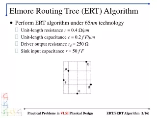
Problem Definition • Problem Definition: • For a given set of clock sinks {S}, and a given set of obstacles {OBS} • Find a zero-skew solution {P} that connected all the sinks in {S} in a 2-D grid such that • {{S} U {P}} ∩ {OBS} = 0 • {S}, {P} and {OBS} is a set of x-y coordinates in 2-D grid • Example solution is show on the right
Algorithm • Five stage algorithm • Each stage has its own detailed algorithm • The entire algorithm will be very heavily based on heuristics
Rough Partition • Objective: • To assemble the partitions such that there is no obstacles in the middle of the partition • Input & Output: • Input: set of sinks {S} and set of obstacles {OBS} with in the boundary of {S} • Output: Bi-partition of {S}, {S1} and {S2} such that • {S1} U {S2} = {S} • {S1} ∩ {S2} = 0
Rough Partition – continue • Rough Partition phase will finish when there is no obstacles left in to be partitioned • This phase is used to avoid as much obstacles as possible • We are calling it “Obstacles Avoidance Partition”
Topology Generation • Objective: • Find the good match on set of sinks from bottom up • Input & Output: • Input: set of sinks {s} in a partition from OAP phase • Output: Tree representation {Ts} of such set of sinks
Routing Tree Construction • Objective: • Construct a set of zero skew trees • Input & Output: • Input: set of partition {P} and its tree representation {Ts} • Output: set of zero skew trees {ZST}
Tree – Bottom up phase • During the Bottom up phase tasks similar to DME is performed
Tree – Top down phase • Top down phase selects the zero skew point
Tree – Routing with Obstacles • At first, try to connect the two point directly • Whenever we meet a obstacle, try contour the obstacle by depth-first searching • try the shortest path corner of the obstacle first
Tree Merging • Bottom up approach • Objective: • To select the “best” matching pair of sub-trees produced in the previous stage • Input & Output: • Input: set of sub-tree {ZTS} • Output: merged tree {MT}
Tree Merging Clock delay
Tree Merging Clock source
Tree Merging • What if? There is no pair that can be connected because of too big skew - Divide 2 trees into 4 trees and retry Final result does not meet the spec - Retry tree merging till the result can meet the spec
Tree Merging • Routing • Will route around obstacles
Tree Balancing • Top down approach • Objective: • To minimize the skew on each clock path • Input & Output: • Input: tree {MT} from Tree Merging phase and set of sinks {S} • Output: balanced skew tree {TB}
Assumptions • Uniform wire size • Same resistance and capacitance per unit of length • Uniform sink size • All sinks has same size, i.e., 1um x 1um
Workload Distribution • All the algorithms were discussed between team members before implementation phase • OAP and topology generation – Jiong Fan • Routing Tree Construction – Sanghoon Kim • Tree Merging – Minsik Cho • Tree Balancing – ?? • To be assigned • May not be implemented • Random Obstacles Generation – ?? • May test with fixed set of obstacles first
Testing methodology • Using the input file for Steiner tree homework • Input file format • ------- Resistance per um • | ---- Capacitance per um • | | • 0.003 2.0e-17 • boundary: 0 0 70000 69984 // Upper left and lower right coordinates of die (um) • nrClkPins= 267 // Total number of nodes • 0 29322 41420 5.9e-14 // Node 1 : position x,y and node capacitance • 1 26208 51579 3.5e-14 // Node 2 • 2 35565 61661 5.3e-14 // Node 3 • . • . • .
Feather improvement • Study the improvement by incorporate wire sizing and buffer insertion in the tree balancing stage • Reduction on clock delay, thus increasing on clock frequency
Reference • “Exact Zero Skew” • Ran-Song Tsay • IEEE Int. Conference on Computer-Aided Design (ICCAD-91), pp. 336- 339, Nov. 1991. • “Zero Skew Clock Routing with Minimum Wirelength” • T.-H. Chao, Y.-C. Hsu, J.-M. Ho, K. D. Boese, and A. B. Kahng, • IEEE Trans. Circuits Syst. -II, pp. 799- 814, 1992. • “More Practical Bounded-Skew Clock Routing” • A. B. Kahng and C.-W. A. Tsao • Proc. 34th ACM/IEEE Design Automation Conf., pp. 594-599, 1997. • “UST/DME: A Clock Tree Router For General Skew Constraints” • C.-W. A. Tsao and C.-K Koh, • Proc. IEEE Intl. Conf. on Computer Aided Design, 2000
Thank you! Thank you!