Download
1 / 1
10 likes | 144 Views
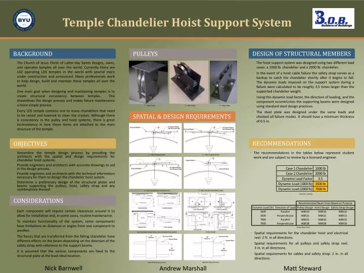
Temple Chandelier Hoist Support System. background. 3 – Way Top Mounted Detail [Front].

E N D
Temple Chandelier Hoist Support System background 3 – Way Top Mounted Detail [Front] The Church of Jesus Christ of Latter-day Saints designs, owns, and operates temples all over the world. Currently there are 142 operating LDS temples in the world with several more under construction and announced. Many professionals work to help design, build and maintain these temples all over the world. One main goal when designing and maintaining temples is to create structural consistency between temples. This streamlines the design process and makes future maintenance a more simple process. Every LDS temple contains one to many chandeliers that need to be raised and lowered to clean the crystals. Although there is consistency in the pulley and hoist systems, there is great inconsistency in how these items are attached to the main structure of the temple. objectives Pulleys considerations Recommendations Each component will require certain clearances around it to allow for installation and, in some cases, routine maintenance. To maintain functionality of the system, some components have limitations on distances or angles from one component to another. The forces that are transferred from the falling chandelier have different effects on the beam depending on the direction of the safety strap with reference to the support beams. It is assumed that the various components are fixed to the structural plate at the least ideal location. Spatial & Design Requirements 1 – Way Hanging Detail Design of Structural members 2 – Way Hanging Detail Small Plate Requirements The hoist support system was designed using two different load cases: a 1000 lb. chandelier and a 2000 lb. chandelier. In the event of a hoist cable failure the safety strap serves as a backup to catch the chandelier shortly after it begins to fall. The dynamic loads imposed on the support system during a failure were calculated to be roughly 3.5 times larger than the supported chandelier weight. Using this dynamic load factor, the direction of loading, and the component eccentricities the supporting beams were designed using standard steel design practices. The steel plate was designed under the same loads and checked all failure modes. It should have a minimum thickness of 0.5 in. 2 – Way Pulley 1 – Way Pulley 3 – Way Pulley Streamline the temple design process by providing the architects with the spatial and design requirements for chandelier hoist systems. Provide engineers and architects with accurate drawings to aid in the design process. Provide engineers and architects with the technical information necessary for them to design the chandelier hoist system. Determine a preliminary design of the structural plates and beams supporting the pulleys, hoist, safety strap and any combinations thereof. Pulley Details Electrical Reel, Safety Strap, Hoist & Cable/Strap Details 3 – Way Top Mounted Detail [side] Big Plate Requirements 4 3 • The recommendations in the tables below represent student work and are subject to review by a licensed engineer. 2 1 Dynamic Loadings Design Beam Sizes • Spatial requirements for the chandelier hoist and electrical reel: 2 ft. in all directions. • Spatial requirements for all pulleys and safety strap reel: 3 in. in all directions. • Spatial requirements for cables and safety strap: 2 in. in all directions. Nick Barnwell Matt Steward Andrew Marshall