Download
1 / 57
610 likes | 936 Views
Mechanical content by way of System Approach. Utilizing Festo Systems. Content Structure: Mechanical Components. Material Basics Fasteners, Nuts and Washers Ball Screws and Power Threads (ACME) Flexible Elements (Belts and Chains) Couplings and Clutches

E N D
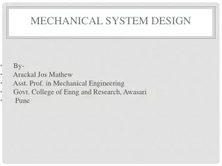
Mechanical contentby way of System Approach Utilizing Festo Systems
Content Structure:Mechanical Components • Material Basics • Fasteners, Nuts and Washers • Ball Screws and Power Threads (ACME) • Flexible Elements (Belts and Chains) • Couplings and Clutches • Elastic (mechanical) Springs • Gears and Gear Trains • Bearings, Guideways and Lubrication • Sealings and Retaining Rings • Keys (Spline Shafts) and Pins • Technical Drawings (Tolerances, Fits, Standards)
Content Structure:Mechanical Components • Material Basics • Fasteners, Nuts and Washers • Ball Screws and Power Threads (ACME) • Flexible Elements (Belts and Chains) • Couplings and Clutches • Elastic (mechanical) Springs • Gears and Gear Trains • Bearings, Guideways and Lubrication • Sealings and Retaining Rings • Keys (Spline Shafts) and Pins • Technical Drawings (Tolerances, Fits, Standards)
Materials Metallic Materials Composites Non-metallic Materials e.g. Sintered Metal (Hard Metal), Concrete, Fibery Glass Ferrous Alloys Natural Materials e.g. Steel, Cast Iron e.g. Wood, Stone, Leather Ceramic Materials Non-natural Materials Non-ferrous Alloys e.g. Glass, Porcelain Aluminium Oxide Light Metals e.g. Magnesium, Aluminium Polymer Materials Noble Metals Heavy Metals e.g. Polyester, Polyamide Plexiglass e.g. Copper , Nickel, Zinc e.g. Gold, Platinum
Material Basics Temperature C° 1536 Liquid Iron A 1400 D Liquid + Austenite C Liquid + Cementite 1200 F 1147 E Austenite 1000 Austenite, Ledeburite Cementite Cementite + Ledeburite G 800 S K 723 P Cementite, Pearlite + Ledeburite 600 Pearlite + Ferrite Pearlite + Cementite 500 0.8 2.06 4.3 6.67 Carbon % 1 2 3 4 5 6 hypo-eutectoid hyper-eutectoid Eutecticum Cast Iron Steel
increases lowers Non-metals (companions to iron) CarbonC Silicium Si PhosphorusP SulphurS Metals (alloying elements) ChromiumCr MolybdenumMo ManganeseMn NickelNi VanadiumV WolframW
Brinell Rockwell Vickers
Example: Unalloyed Steel ProportionalLimit Rupture or Breaking Strength Yield Strength Ultimate or Tensile Strength Hook‘s Law Strain (%) Elastic Behavior Plastic Behavior
High-Strength Steel Stress (N/mm2) Unalloyed Steel Aluminium Alloy Strain (%)
Initial Hammer Position Impact Test Scale Impact Specimen zoom-in End of the Swing Impact Specimen Areas of Fraction
4 1 5 2 • 1 Hexagon Bolt (pull-in) • Socket–Head Cap Screw • Stud Bolt • Fit Bolt • Anti–Fatique Bolt 3
10. Which of the following screw lockings are friction based? A 1, 2 and 7 B 3, 4 and 5 C 6, 8 and 9 D 7, 10 and 11 E All are friction based x x
Thread Angle 60° Minor (Root) Diameter Major Diameter d1 d d2 P Mean (Pitch) Diameter Pitch
15. Which statements about the pictured thread are correct? A The thread angle for metric threads is = 55° B For manufacturing the diameter d2 is not important C No 1 is the pitch of the thread D The diameter d1 leads to the thread designation M E The diameter d2 is the root diameter of the thread x x
Screw Guided Balls Nut
30° 55-60° Power Thread (ACME) Ball Screw Fastener Thread
13. Which of the following descriptions about the pictured component is correct? A It is a Ball Screw for translating rotational motion to linear motion B It is a Trapezoidal Thread Rod for translating linear motion to rotational motion C It is a Worm Gear for translating rotational motion to linear motion D It is a Flexible Shaft for transmitting torques E It is a Spline Shaft for transmitting torques x
Simple Drive System North Gear Ltd. V-Belt Drive Gearbox DC-Motor Tire-Coupling
11. Whatis the pictured component called? A Shock Absorber B Tire Coupling C Internal Expanding Clutch D Journal Bearing E Spherical Roller Bearing x
30+0.25 36+0.5 5 B A Rz 4 Ø25k6 Ø25k6 Ø25H7 Ø25H7 Ø25k6 Ø36h11 Ø71 Ø42 Ø64 x A 1.5 y 1.3H13 50 84+0.3 2x45° 24±0.05 146 A - A 0.5 B x Rz 4 = 8h9 8P9 8P9 y Rz 1.6 = 28-0.2 22+0.2
Clearance or Transision Clearance or Transision Interference
5-0.15 5H7 -0.05 5s6 5+0.15 +0.05 Tolerances Fits
½ ES ½ es ½ EI ½ ei Shaft Dmax Dmin dmax dmin Basic Size d=D ½ ei ½ EI ½ es ½ ES Hole ES = Hole upper Deviation Hole Tolerance Zone es = Shaft upper Deviation EI = Hole lower Deviation Shaft Tolerance Zone ei = Shaft lower Deviation