Download

1 / 16
160 likes | 262 Views
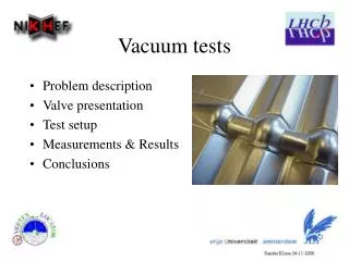
Vacuum tests for CLIC module prototypes. Outline: Reminder: specification and specificity Tests on first Lab. Module Configuration Leak tests and consequences Representative vacuum tests on accelerating structure mock-up Towards next module prototype New vacuum system configurations

E N D
Vacuum tests for CLIC module prototypes • Outline: • Reminder: specification and specificity • Tests on first Lab. Module • Configuration • Leak tests and consequences • Representative vacuum tests on accelerating structure mock-up • Towards next module prototype • New vacuum system configurations • Vacuum tests on accelerating structure mock-up • Thermal outgassing tests on SiC • Conclusion C. Garion
Specification and specificity • The vacuum specification for the CLIC two beam modules is: • 1.3.10-9 mbar for the main beam [EDMS 992778] • 4.10-8 mbar for the drive beam [CLIC CDR, Section 4.4] • The vacuum system is unbaked. • System with low conductances (typical geometrical size ~ 10 mm) and large areas (~0.5 m2/AS). C. Garion
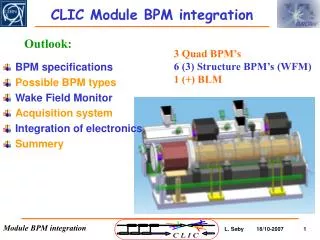
Vacuum system configuration on 1st Lab. module • Central manifold equipped with: • 2 ports for NEG cartridge pumps (2* 2000 l/s H2) • 1 port for ion pump (~60 l/s) for methane and noble gases • 1 port for mobile pumping group Transverse connections to accelerating structures and PETS conductance limited system (~40 l/s) Transverse connections to RF loads C. Garion
Leak tests on 1st Lab. module Two main leaks in the 10-5mbar.l/s on accelerating structures: few others fixed with araldite and one on the RF network. • Consequences: • Main beam isolated from the vacuum system with blank gasket • No UHV tests C. Garion
Representative vacuum tests on accelerating structure mock-up Penning Gauge Turbomolecular pump Insulation valve Pirani Gauge Vacuum manifolds (25*28, 30*30 mm2) Cap with Indium sealing Penning Gauge C. Garion
Representative vacuum tests on accelerating structure mock-up Evolution of pressure Pressure profile along beam axis after 100h of pumping • Good agreement between the measurements and the simulation • Non significant influence of manifold size • 7.10-9 mbar is reached after 100 hours of pumping Pressure field after 100h of pumping C. Garion
Towards next module prototype - New vacuum system configurations NEG cartridge pumps + small ion pumps installed on (in) accelerating structures and PETS. Small manifold above the main beam, connected to the RF loads, equipped with pumping ports (fixed pumps and mobile pumping group) Nextorr pump from SAES • Advantages: • Pumping speed not (PETS) or much less (AS) limited by the pumping port conductance • No transverse vacuum force on the accelerating structures and PETS • More compact C. Garion
Towards next module prototype -Vacuum tests on accelerating structure mock-up Penning Gauge Insulation valve Vacuum manifold Turbomolecular pump Compact NEG and ion pump C. Garion
Towards next module prototype - Vacuum tests on accelerating structure mock-up Pressure field after 100h of pumping Evolution of pressure • Good agreement between the measurements and the simulation • 3.10-9 mbar is reached after 100 hours of pumping C. Garion
Towards next module prototype - Vacuum tests on accelerating structure mock-up Diaphragm (pumping speed ~ 1.5l/s) C. Garion
Towards next module prototype - Vacuum tests on accelerating structure mock-up ~10-9 mbar after 100h. 5.9.10-10 mbar Pump down curve (bakeout of Te and ion pump not represented). C. Garion
Towards next module prototype – Thermal outgassing tests Thermal outgassing measurements of SiC. Sample have been tested after heat treatment corresponding to soldering cycle. Schematic diagram of the throughput method Thermal outgassing for unbaked sample Pump down curve • Factor ~ 40 higher than copper of stainless steel (at least after few hours of pumping). • Measurement on baked samples in preparation C. Garion Sample P2 C P1 S
Conclusions • Vacuum system for the first module in Lab is based on a central manifold equipped with vacuum pumps. This is not anymore the preferred technical solutions. • No UHV tests have been carried out due to external leaks. • Vacuum tests have been performed on a dedicated accelerating structure mock-up showing: • Good agreement between simulations and measurements • Interest of small mini-pump connected directly on the accelerating structures. • SiC outgassing rate is significant (at least at the beginning of pumping). • Next module, based on “mini pumps”, should also integrate, at least one accelerating structure, with all loads. C. Garion
Towards next module prototype - Vacuum tests on accelerating structure mock-up Measurement on the additional manifold is representative of average pressure along the beam axis but the test set-up introduces an additional gas load C. Garion