Download

1 / 13
130 likes | 290 Views
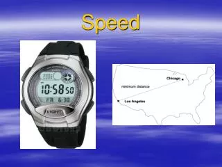
SPEED measurements. The angular velocity of rotating machine is usually expressed in radian per seconds, ω ( rad /sec) or revolutions per minutes, N, (RPM ). ω =2 π N/60 Eq. 11.1 A tachometer is an instrument, which measures directly the angular velocity of a rotating shaft.

E N D
The angular velocity of rotating machine is usually expressed in radian per seconds, ω (rad/sec) or revolutions per minutes, N, (RPM). • ω=2πN/60Eq. 11.1 • A tachometer is an instrument, which measures directly the angular velocity of a rotating shaft.
1. MECHANICAL TACHOMETER • Two masses are mounted on leaf springs which are attached at one end to a driven shaft. • The other ends of the springs are attached to a grooved collar which can slide on the shaft and move a pointer, Fig. 11.1. • As speed increases the centrifugal force on the masses increases • (i. e. centrifugal force=mrω2, where m is the mass, r is the radius from the center of motion and ω is the angular velocity), • Thus causing the masses to move outwards and the sliding collar to move up the shaft. The movement of the collar is transmitted through a quadrant and pinion to a pointer. This instrument may be used to measure a rotational speeds up to 40 000 rpm with an accuracy of ±1%.
2. Dc OR AC TACHOGENERATOR • D.C. or A.C. generators are used to measure the angular velocity. • The generator shaft is fixed with the driven shaft. • The output voltage is proportional to the rotational speed. • The output voltage may be measured using a voltmeter calibrated in revolution per minutes. • These instruments may be used up to 5000 RPM with an accuracy of ±2%.
3. STROBOSCOPE • The instrument operates on the principle that if a repeating event is only viewed when at one particular point in its cycle it appears to be stationary. • A mark is made on the rotating shaft, and a flashing light is subjected on the shaft. • The frequency of the flashing is adjusted so that there is one very short flash per revolution. • The observer will see the mark on the same position standing still.
A rotating shaft will also appear to be stationary if the flash frequency is any multiple of the shaft speed. • A single mark on a shaft that is rotated at 1000 RPM will make two revolutions between flashes if the flashes at a rate of 500 flash per min. • The shaft may make any number of complete revolutions between flashes and still appear to be stationary. • The above shaft will appear to be stationary at 1000flashes per min., and also at 500, 333 1/3,250, etc. • If the frequency of the flashing light is twice the shaft speed, a single mark on the rotating shaft will appear to be two standing marks 180 degrees apart.
A suitable technique for determining the shaft speed is to gradually increase the frequency of flashing from a small value until the rotating shaft appears to be stationary and note the frequency. • The flash frequency is then doubled if there is still only one apparent stationary image the frequency is again doubled. • This procedure is continued until two images appear 180 degrees apart. When these two images first appear the flash frequency is twice the speed of rotation. • Stroboscopes are used to measure angular speed between 600 and 20000 RPM. Its advantage is that it does not need to make contact with the rotating shaft.
4. ELECTRONIC TACHOMETER 4.1 Inductive Tachometer • A typical system using an inductive pick-up is shown in Fig. 11.4. • The teeth on the wheel changes the inductance of the magnetic coil as it passes in front of it. • This will produces an e. m. f. change in the form of a pulse. • The pulses are fed into a digital counter, which counts the number of pulses for some preset time interval.
4.2 Photoelectric Tachometer • An incident light ray is directed to a small reflecting surface on the rotating shaft. • The reflecting light rays fall on the photodiode . • The photodiode produces a voltage pulses, which is then amplified and counted. • The shaft speed may be determined by measuring the time between two successive pulses. • The speed will be the reciprocal of this time. Another way, is to count the No. of pulses in a preset time interval and divide the no of pulses by the time interval
Note: PHOTO VOLTAIC CELL • The photovoltaic-cell principle is illustrated in Fig. 11.6. The sandwich construction consists of a metal base plate, a semiconductor material, and a thin transparent metallic layer. • This transparent layer may be in the form of a sprayed. • When light strikes the barrier between the transparent metal layer and the semiconductor material, a voltage is generated as shown