Download
1 / 24
240 likes | 358 Views
Progress in the Study of an X-Ray FEL Oscillator. Kwang-Je Kim ANL & the Univ. of Chicago 31 st Int. FEL Conference August 23-28, 2009 BT Convention Center Liverpool, UK. LINAC Coherent Light Source LCLS. Project start 1999. 2011. SCSS

E N D
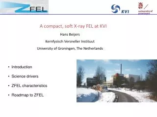
Progress in the Study of an X-Ray FEL Oscillator Kwang-Je Kim ANL & the Univ. of Chicago 31st Int. FEL Conference August 23-28, 2009 BT Convention Center Liverpool, UK
LINAC Coherent Light Source LCLS Project start 1999 2011 SCSS SPring-8 Compact SASE Source European XFEL Facility 2014 Era of Hard X-Ray FEL has Arrived (April, 2009) LCLS August,2008 March, 2009 I=500 A I=3000A April 10, 2009 User experiment September, 2009 LCLS, April 2009
(Hard) X-Ray FEL Oscillator • An x-ray pulse trapped in optical cavity, meets an electron bunch inside undulator gain • Zig-zag path cavity allows wavelength tuning • Exponential increase of the intensity, if gain > loss • Steady state when gain approaches loss at high intensity • XFELO with crystal cavity proposed in 1984 by Collela and Luccio, has been in hibernation, resurrected in 2008 (KJK, S. Reiche, Y. Shvyd’ko, PRL 100, 244802 (2008)
FEL Modeling(R. Lindberg, et. al., WEPC40 ) • Analytical • 3D Gain calculation (KJK),1D supermode theory (G. Dattoli, P. Elleaume), initial noise-seed estimate (R. Lindberg) • Simulation • Combine single-pass codes with propagation and reflection in x-ray cavity with correct crystal response • GENESIS: 3D (S. Reiche) slow • GINGER: 2D (W. Fawley, R. Lindberg) • Reduced 1-D code by an approximate treatment of the transverse effect (R. Lindberg & KJK, PRSTAB, 2009; G. Penn, et al.,MOPC43) • Recent work: estimates of harmonics • 3rd harmonic output ~10-3 – 10-4 of fundamental (R. Lindberg)
X-Ray OpticsChallenges &Progresses • Quality of diamond crystals • Must be perfect with reflectivity 98-99%,but only in a small volume < 0.5x0.5x0.1 mm3 • Heat load & shock wave on crystal: Can DE< 1 meV maintained? • Absorption: 1 mJ for 1-ps pulse in 100x100 mm2, 1 MHz rep rate • Initial heat load simulation performed (H. Sinn) • Inter-pulse problem can be solved by cooling, T <100K • Intra-pulse problem is probably OK • Crystal stability • Angular stability <10 nrad, position< 3 mm. • Pilot null-detection FB at APS indicates that 50 nrad stability for f< 2Hz is feasible • Grazing-incidence, curved mirror for focusing • High reflectivity (>95%) and minimal wavefront distortion
XFELO Ultra-Narrow Bandwidth: Deg ~ 1 meV or Deg /eg ~1×10⁻⁷
Technology R&D for XFELO • X-ray optics • Injector development • These R&Ds will advance the state-of–the-arts, benefiting general accelerator and x-ray optics technology
Tunable X-ray Cavity • Two crystal scheme has a very limited tuning since q must be kept small • A four crystal scheme is tunable R. M.J.Cotterill, APL, 403,133 (1968) KJK & Y. Shvyd’ko, PRSTAB (2009) • Any interesting spectral region can be covered by one chosen crystal material • Simplify the crystal choice Diamond as highest reflectivity & best mechanical and thermal properties
Quality of Diamond Crystals • Require high quality (dislocation-free, etc) in a volume (1-2) mm2× (40-100) mm • Need to prove 98-99 % reflectivity APS experiment with C (995), EH=23.8 keV
Reflectivity and Spectral Width Measurement at APS Sector 30in good agreement with TheoryMarch, 2009 C(995) EH=23.765 keV S. Stoupin, Y. Shyv’dko & A. Cunsolo
Heat Load Problem • As an intracavity x-ray pulse hit a crystal, r-dependent temperature rise dT crystal expansion dE/E = bdT (dL/L=b dT/T) dE/E<<10-7? • Heat load simulation by H. Sinn • Due to high thermal-diffusivity, Inter-pulse effect can be made small if T< 100K (high-diffusivity) • Intra-pulse effect dE/E~ 5-10 × 10-7 if the expansion time scale << pulse duration (~ps). If >>,dE/E<<10-7 • Need further study b S. Stoupin and Y. Shvyd’ko, March 2009
Null-Detection FB at APS Sector 30(S. Stoupin, F. Lenkszus, Y. Shvy’dko,..) IC3 IC1 HRM IC2 IC0 • The stability of IC3 signal indicates the angular stabilization of the 3rd crystal pair within 50 nrad is achieved for f < 2 Hz PZT IC0 IC1 IC3 IC2 Feedback correction signal
Grazing Incidence, Curved Mirror • JTEC • Developing a technique combining elastic emission machining (EEM, slow) and electrolytic in-process dressing (ELID, fast) to fabricate an “arbitrary” surface, such as ellipsoidal, to <nm height error and 0.25 mrad figure error • Such mirrors are sought after by “every body” in SR business • Other ways of focusing • Curved crystal surface, CRL,.. H. Mimura, et. al. RSI 79, 083104, 2008
Prototype X-Ray Cavity at an APS Beamline • About 1/5 model of an XFELO cavity • Adjust the distance M1-M2 to control the stability • Adjust the round trip path length to match/mismatch the spacing (46m) between the APS x-ray pulses • Test overall reflectivity, crystal and mirror stabilization, transverse mode profile ~24 m
Electron Beam Quality Requirements • The requirements: • Normalized rms emittance < 0.2 mm-mr • Bunch charge < 50 pC • Bunch length (rms)~ 1 ps (transform-limited spectral width << mirrror bandwidth) Peak current ~10-20 A • Energy spread < 2.10-4 • Bunch rep rate > 1 MHz • The ERL injector in high coherence mode (Cornell) satisfies the requirements if the 750 kV DC voltage can be achieved • The LCLS injector @ low charge mode produces similar e-beams but at lower rep rate • We are developing a novel type of injector
Injector Design: A New Paradigm • Current paradigm of injector design laser driven rf photocathode • Remove elaborate bunching steps • High-peak current from start, large space charge degradation, require emittance compensation • Successful for hi gain FELs • For low intensity & ultra-low emittance for XFELO thermionic cathode inside low freq. RF cavity • SCSS/Spring-8 success of pulsed DC gun • The injector can also be configured to produce beams suitable for ultrafast (a few fs) SASE (J. Rosenzweig,..)
10 – monochromator, 600 MHz; 11 –velocity buncher, 300 MHz; 12 – solenoids; 13 – SC linac, 66 MeV, f=400 MHz. 14 – high-harmonic cavity (1300 MHz); 15 – bunch compressor – I; 16 – SC linac, 546 MeV, f=1300 MHz. 17 – bunch compressor – II; 1 – RF cavity with thermionic cathode, 100 MHz, 1 MV; 2 – focusing solenoid; 3 - RF chopper to form bunch repetition rate (< 3 MHz); 4 – quadrupole; 5 – beam dump; 6 – slits handling high power; 7 – chicane and slits (6) as an energy filter; 8 – quadrupole triplet; 9 – 100 MHz rf cavity; • Critical R&D items • Small diameter cathode • 1 MV voltage with 100MHz cavity • High power slits
Ultrashort, Ultralow Emittance for Ultrafast SASE • Same general configuration • Adjust the slits in the energy filter. • The second bunch compressor is not required • Introduced an additional harmonic cavity operating at 30 GHz with very low voltage (4 kV). • This is a preliminary study & another factor compression by a factor of 2 appears to be feasible.
Test Bench for Thermionic E-Gun Assembly with Pulsed DC Voltage Pepper pot plate 300 kV HV isolator Current transformer Movable FC Scintillator - 300 kV pulsed PS Anode AC heater PS Output window Cathode assembly CCD-camera HV platform Triggering unit
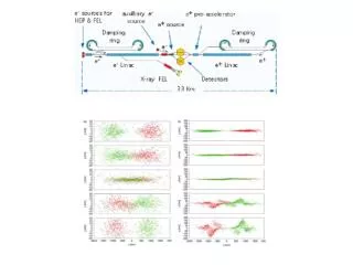
XFELO-Facility • Bunch intensity is low SCRF accelerator can be operated in CW • Recirculation without energy recovery can save SCRF linac cost. Required energy 6-8 GeV • 20 MHz injector 20 XFELOs
Facility Options Recirculation saves linac cost, but the requires elaborate optics. Maybe 1 recirculation? Straight linac will be most versatile, with possibility of both XFELO and ultrafast SASE
XFELO Study Group • Modeling/Simulation • R. Lindberg, W. Fawley, S. Reiche • Injector • P. Ostroumov, KJK,B. Mustapha, Ph. Piot, S. Kondrashev, A. Nassiri, G. Waldschmidt, D. Capatina • LBNL on 100 MHz cavity (F. Sannibale, J. Stable, J. Corlett,..) • RIKEN/Spring-8 on cathode assembly ( T. Shintake, K. Togawa,..) • X-ray Optics • Y. Shvyd’ko, S. Stoupin, D. Shu, A. MacRander, L. Assoufid, H. Sinn (DESY) • RIKEN/Spring-8 (T. Ishikawa, ..)