Download
1 / 47
570 likes | 868 Views
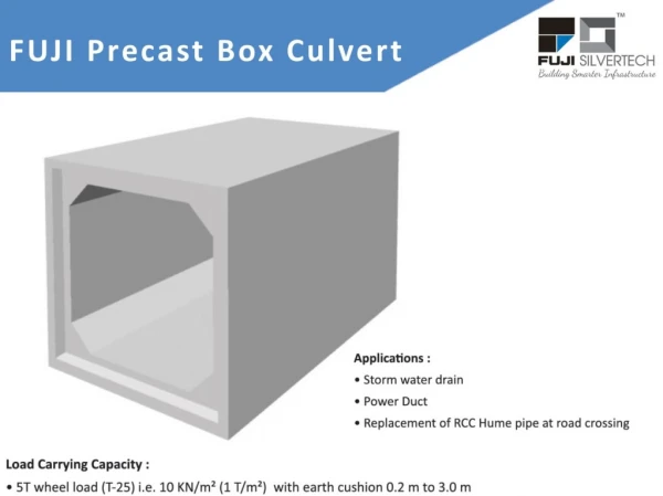
RCC BOX CULVERT SIZE 6m X 4m With 2m Earth Cushion FOR 25t LOADING - 2008. INTRODUCTION. Four-sided culverts are typically referred to as box culverts. APPLICATIONS. Box culverts Short-span bridges (over highways, waterways railways, for golf courses, etc .)

E N D
RCC BOXCULVERTSIZE 6m X 4m With 2m Earth CushionFOR 25t LOADING - 2008 DESIGNED AT RESEARCH DESIGN AND STANDARDS ORGANISATION LUCKNOW
INTRODUCTION Four-sided culverts aretypicallyreferred toasboxculverts DESIGNED AT RESEARCH DESIGN AND STANDARDS ORGANISATION LUCKNOW
APPLICATIONS Boxculverts • Short-span bridges (over highways, waterways railways, for golf courses, etc.) • Conveyance of storm water, sewage or industrial wastes (storm drains) • Tunnels (to house conveyers, utilities, etc; to provide access, escape routes, etc.) • Detention DESIGNED AT RESEARCH DESIGN AND STANDARDS ORGANISATION LUCKNOW
APPLICATIONS Benefits • Box culverts can be made in large sizes to accommodate increased flow rates and capacities. • Boxes can be set with 0m to 10m of cover. DESIGNED AT RESEARCH DESIGN AND STANDARDS ORGANISATION LUCKNOW
STORMWATER CONVEYANCE Typical small stream crossing DESIGNED AT RESEARCH DESIGN AND STANDARDS ORGANISATION LUCKNOW
TUNNELS Fast and economical method for tunnels under roadways, as in this golf cart tunnel. DESIGNED AT RESEARCH DESIGN AND STANDARDS ORGANISATION LUCKNOW
TUNNEL & ESCAPE ROUTES Provide for emergency egress, as with this tunnel underneath a warehouse and distribution center. DESIGNED AT RESEARCH DESIGN AND STANDARDS ORGANISATION LUCKNOW
STORMWATER DETENTION Multicell box culvert installation to economically provide storage of storm water runoff. DESIGNED AT RESEARCH DESIGN AND STANDARDS ORGANISATION LUCKNOW
DESIGN Design of RCC single Box culvert: Objective: • To understand the basic concept of design of RCC box culvert. • To use the provision of IRS Concrete Bridge code, Bridge rule and IRS Bridge Substructure and Foundation Code. • RCC box culvert of size …….. with fill height……… has been used as an example for explaining the concepts. DESIGNED AT RESEARCH DESIGN AND STANDARDS ORGANISATION LUCKNOW
Structures • Box culvert is a monolithic rigid structure consisting mainly of top slab, bottom slab and side vertical walls. • The top slab of box culvert is subjected to earth above it, ballast, track structure and live load. The side walls are subjected to earth pressure from outside. The bottom slab supported on soil/ throughout and is subjected to water load from top and uniform pressure of soil from bottom. DESIGNED AT RESEARCH DESIGN AND STANDARDS ORGANISATION LUCKNOW
Main components of design: • Section • Data • Calculation of loads • Bending moment and SF calculation • Design • Detailing • Check of shear • Check of crack width etc. DESIGNED AT RESEARCH DESIGN AND STANDARDS ORGANISATION LUCKNOW
Advantages • The box is a rigid structure and both the horizontal and vertical members are made of soils slabs. Hence it is sample in construction. • The loads are distributed almost uniformly over a wider area as the bottom slab serves as a raft, this reducing pressure of soil. • Faster construction by adopting segmental construction with pushing technique. DESIGNED AT RESEARCH DESIGN AND STANDARDS ORGANISATION LUCKNOW
Data collection • Site requirement • Material properties • Geometrical properties • Other data • Site requirement • Bed level • Formation level • Loading standard DESIGNED AT RESEARCH DESIGN AND STANDARDS ORGANISATION LUCKNOW
Material properties • Grade of concrete (M-30/M-35) • Grade of steel (Fe415) • Density of concrete /steel. • Geometrical properties • Span of the box • Height of the box • Fill height • Thickness of top slab • Thickness of bottom slab • Thickness of vertical wall • Thickness of wearing coat DESIGNED AT RESEARCH DESIGN AND STANDARDS ORGANISATION LUCKNOW
Other data /assumption • Ballast cushion • Formation width • Details of track structure • Bearing capacity of soil • Number of track • Design curvature DESIGNED AT RESEARCH DESIGN AND STANDARDS ORGANISATION LUCKNOW
Various loads considered • Dead load • Super imposed dead load • Live load • Earth pressure • Earth pressure due to surcharge • CDA • Curvature of ………. DESIGNED AT RESEARCH DESIGN AND STANDARDS ORGANISATION LUCKNOW
Load combination considered • DL+EP+LL one span and both approaches with 1Ka • DL+EP+LL one span and both approaches with 2Ka • DL+EP+LL one span and one approach with 1Ka • DL+EP+LL one span and one approach with 2Ka • DL+EP (No live load) with 1Ka • DL+EP (No live load) with 2Ka • Salient features • Ballast cushion (350mm) • Active earth pressure as per Rankie’s formula • Working stress method • Clear cover (50mm) DESIGNED AT RESEARCH DESIGN AND STANDARDS ORGANISATION LUCKNOW
DESIGNED AT RESEARCH DESIGN AND STANDARDS ORGANISATION LUCKNOW
DESIGN METHODOLOGY • Take suitable size of box culvert for a particular site. Here as example 6m X 4m WITH 2m earth fill case has been taken • Detailed design calculations are carried out in next slide. DESIGNED AT RESEARCH DESIGN AND STANDARDS ORGANISATION LUCKNOW
DESIGN METHODOLOGY SPAN = 6m CLEAR HEIGHT = 4m (Assumed thickness of top & bottom slab and vertical walls) TOP SLAB TICKNESS = 60 cm BOTTOM SLAB TICKNESS = 60cm VERTICAL WALLS THICKNESS = 60cm CONCRETE GRADE = M35 STEEL GRADE = Fe 415 WEIGHT OF TRACK & BALLAST = 5.5 t/m BALLAST CUSHION = 0.350m WEARING COAT THICKNESS = 0.15m FORMATION WIDTH = 6.85m INTENSITY OF SURCHARGE = 13.70 t/m ANGLE OF INTERNAL FRICTION OF SOIL = 35 Degree DESIGNED AT RESEARCH DESIGN AND STANDARDS ORGANISATION LUCKNOW
DESIGN METHODOLOGY EFFECTIVE SPAN = EFFECTIVE HEIGHT = EQUIVALENT UDL FOR 6.65m EFFECTIVE SPAN = =94.298 t CDA = =0.782 CDA SUBJECTED TO EARTH FILL>900mm = =0.202 EQUIVALENT UDL WITH CDA = t CLEAR DISPERSION WIDTH = SLEEPER WIDTH+FILL+L/2 = 8.10m DESIGNED AT RESEARCH DESIGN AND STANDARDS ORGANISATION LUCKNOW
DESIGN METHODOLOGY LIVE LOAD = = DEAD LOAD CALCULATION:- Wt OF TOP SLAB = WtOF EARTH CUSHION = WtOF TRACK & BALLAST= TOTAL DEAD LOAD =6.010 TOTAL LOAD ON TOP SLAB =8.114 DESIGNED AT RESEARCH DESIGN AND STANDARDS ORGANISATION LUCKNOW
DESIGN METHODOLOGY Wt OF BOTTOM SLAB = Wt OF VERTICAL WALLS = Wt OF WEARING COARSE = TOTAL LOAD ON BOTTOM SLAB = 11.779 COEFFICIENT OF ACTIVE EARTH PRESSURE Ka 2Ka SIDE PRESSURE CALCULATION Ht. FROM F.L. TO CENTER OF TOP SLAB DESIGNED AT RESEARCH DESIGN AND STANDARDS ORGANISATION LUCKNOW
DESIGN METHODOLOGY Ht. FROM F.L. TO CENTER OF BOTTOM SLAB DISPERSION WIDTH FOR TOP SLAB DISPERSION WIDTH FOR BOTTOM SLAB LATERAL PRESSURE OF SOIL ON TOP SLAB(2Ka) FOR 1Ka LATERAL PRESSURE OF SOIL ON BOTTOM SLAB(2Ka) 7.183 FOR 1Ka 3.591 DESIGNED AT RESEARCH DESIGN AND STANDARDS ORGANISATION LUCKNOW
DESIGN METHODOLOGY SIDE PRESSURE ( Lat.Pr. due to D.L + L.L + E.Pr.) SIDE PRESSURE @ CENTER OF TOP SLAB WITH 2Ka WITH 1Ka SIDE PRESSURE @ CENTER OF BOTTOM SLAB WITH 2Ka WITH 1Ka SIDE PRESSURE (Lat. Pr. due to D.L+E.P) SIDE PRESSURE @ CENTER OF TOP SLAB WITH 2Ka WITH 1Ka DESIGNED AT RESEARCH DESIGN AND STANDARDS ORGANISATION LUCKNOW
DESIGN METHODOLOGY SIDE PRESSURE @ CENTER OF BOTTOM SLAB WITH 2Ka WITH 1Ka • CALCULATE MAX BENDING MOMENT BY MOMENT DISTRIBUTION METHOD FOR LOAD COMBINATION CONSIDERED AS • DL+EP+LL one span and both approaches with 1Ka • DL+EP+LL one span and both approaches with 2Ka • DL+EP+LL one span and one approach with 1Ka • DL+EP+LL one span and one approach with 1Ka • DL+EP+LL one span and one approach with 1Ka DESIGNED AT RESEARCH DESIGN AND STANDARDS ORGANISATION LUCKNOW
DESIGN METHODOLOGY • DL+EP (No live load) with 1Ka • DL+EP (No live load) with 2Ka MAX DESIGN MOMENT DESIGNED AT RESEARCH DESIGN AND STANDARDS ORGANISATION LUCKNOW
DESIGN METHODOLOGY SHOWING MOMENTS AS LINE DIAGRAM OF BOX CULVERT +26.698 -32.084 -20.893 -16.326 -16.326 +VE - 6.773 +VE - 6.773 +35.858 -32.084 -32.084 DESIGNED AT RESEARCH DESIGN AND STANDARDS ORGANISATION LUCKNOW
DESIGN METHODOLOGY DESIGNED AT RESEARCH DESIGN AND STANDARDS ORGANISATION LUCKNOW
DESIGN METHODOLOGY DESIGNED AT RESEARCH DESIGN AND STANDARDS ORGANISATION LUCKNOW
DESIGN METHODOLOGY SHEAR FORCE & SHEAR REINFORCEMENT CALCULATION:- EUDL FOR SHEAR WITH CDA = t LIVE LOAD TOTAL LOAD ON TOP SLAB (DL + LL) TOTAL LOAD ON BOTTOM SLAB DESIGNED AT RESEARCH DESIGN AND STANDARDS ORGANISATION LUCKNOW
DESIGN METHODOLOGY TOP SLAB SHEAR FORCE =Balancd End Moment Shear TOP SLAB SHEAR STRESS PERCENTAGE OF STEEL PERMESSIBLE SHEAR STRESS DESIGNED AT RESEARCH DESIGN AND STANDARDS ORGANISATION LUCKNOW
DESIGN METHODOLOGY BALANCE SHEAR FORCE DIA OF SHEAR BAR SINCE SHEAR REINFORCEMENT IS NOT REQUIRED MIN REINFORCEMENT SPACING PROVIDED SPACING OF SHEAR LINK = 200mm (TWICE OF DISTRIBUTORS) DESIGNED AT RESEARCH DESIGN AND STANDARDS ORGANISATION LUCKNOW
DESIGN METHODOLOGY BOTTOM SLAB SHEAR FORCE =Balancd End Moment Shear BOTTOM SLAB SHEAR STRESS PERCENTAGE OF STEEL PERMESSIBLE SHEAR STRESS DESIGNED AT RESEARCH DESIGN AND STANDARDS ORGANISATION LUCKNOW
DESIGN METHODOLOGY BALANCE SHEAR FORCE DIA OF SHEAR BAR CALCCULATION OF SHEAR BAR SPACING BY CONSIDERING 200mm SPACING AND 5 LINK PER METER • MIN REINFORCEMENT SPACING • 0.75d • σSv x Asv x d / V1 • AND 450mm PERMISSIBLE SPACING = MIN OF ABOVE 4 CASES =407.425mm PROVIDED SPACING OF SHEAR LINK ALONG THE BARREL AS WELL AS ALONG SPAN= 200mm (TWICE OF DISTRIBUTORS) DESIGNED AT RESEARCH DESIGN AND STANDARDS ORGANISATION LUCKNOW
DESIGN METHODOLOGY VERTICL WALL SHEAR FORCE =(Max.of Mad-Mda,Mbc-Mcb)/Effective Ht+Lat. Pressure Diff X CearHt X 0.5 X 7/10 VERTICL WALL SHEAR STRESS PERCENTAGE OF STEEL PERMESSIBLE SHEAR STRESS DESIGNED AT RESEARCH DESIGN AND STANDARDS ORGANISATION LUCKNOW
DESIGN METHODOLOGY BALANCE SHEAR FORCE DIA OF SHEAR BAR SINCE SHEAR REINFORCEMENT IS NOT REQUIRED MIN REINFORCEMENT SPACING PROVIDED SPACING OF SHEAR LINK ALONG THE BARREL AS WELL AS ALONG HEIGHT = 200mm (TWICE OF DISTRIBUTORS) DESIGNED AT RESEARCH DESIGN AND STANDARDS ORGANISATION LUCKNOW
DESIGN METHODOLOGY SHEAR CHECK AFTER HAUNCH TOP SLAB SHEAR FORCE =Balancd End Moment Shear TOP SLAB SHEAR STRESS PERCENTAGE OF STEEL PERMESSIBLE SHEAR STRESS DESIGNED AT RESEARCH DESIGN AND STANDARDS ORGANISATION LUCKNOW
DESIGN METHODOLOGY SHEAR CHECK AFTER HAUNCH BALANCE SHEAR FORCE CALCCULATION OF SHEAR BAR SPACING BY CONSIDERING 200mm SPACING AND 5 LINK PER METER • MIN REINFORCEMENT SPACING • 0.75d • σSv x Asv x d / V1 • AND 450mm PERMISSIBLE SPACING = MIN OF ABOVE 4 CASES =399 mm PROVIDED SPACING OF SHEAR LINK ALONG THE BARREL AS WELL AS ALONG SPAN= 200mm (TWICE OF DISTRIBUTORS) DESIGNED AT RESEARCH DESIGN AND STANDARDS ORGANISATION LUCKNOW
DESIGN METHODOLOGY SHEAR CHECK AFTER HAUNCH BOTTOM SLAB SHEAR FORCE =Balancd End Moment Shear BOTTOM SLAB SHEAR STRESS PERCENTAGE OF STEEL PERMESSIBLE SHEAR STRESS DESIGNED AT RESEARCH DESIGN AND STANDARDS ORGANISATION LUCKNOW
DESIGN METHODOLOGY BALANCE SHEAR FORCE DIA OF SHEAR BAR CALCCULATION OF SHEAR BAR SPACING BY CONSIDERING 200mm SPACING AND 5 LINK PER METER • MIN REINFORCEMENT SPACING • 0.75d • σSv x Asv x d / V1 • AND 450mm PERMISSIBLE SPACING = MIN OF ABOVE 4 CASES =395 mm PROVIDED SPACING OF SHEAR LINK ALONG THE BARREL AS WELL AS ALONG SPAN= 200mm (TWICE OF DISTRIBUTORS) DESIGNED AT RESEARCH DESIGN AND STANDARDS ORGANISATION LUCKNOW
DESIGN METHODOLOGY SHEAR CHECK AFTER HAUNCH VERTICL WALL SHEAR FORCE =(Max.of Mad-Mda,Mbc-Mcb)/Effective Ht+Lat. Pressure Diff X CearHt X 0.5 X 7/10 VERTICL WALL SHEAR STRESS PERCENTAGE OF STEEL PERMESSIBLE SHEAR STRESS DESIGNED AT RESEARCH DESIGN AND STANDARDS ORGANISATION LUCKNOW
DESIGN METHODOLOGY BALANCE SHEAR FORCE DIA OF SHEAR BAR SINCE SHEAR REINFORCEMENT IS NOT REQUIRED MIN REINFORCEMENT SPACING 0.75d PERMISSIBLE SPACING = MIN OF ABOVE 4 CASES =399 mm PROVIDED SPACING OF SHEAR LINK ALONG THE BARREL AS WELL AS ALONG HEIGHT = 200mm (TWICE OF DISTRIBUTORS) DESIGNED AT RESEARCH DESIGN AND STANDARDS ORGANISATION LUCKNOW
DESIGN METHODOLOGY DESIGN CONSTANTS NEATRAL AXIS CONSTANT =0.319 LEVER ARM CONSTANT = 0.894 M.R. CONSTANT = 16.967 DESIGNED AT RESEARCH DESIGN AND STANDARDS ORGANISATION LUCKNOW
DESIGN METHODOLOGYTOTAL PRESSURE ON SOIL(by dispersion at Bottom Slab through walls) DESIGNED AT RESEARCH DESIGN AND STANDARDS ORGANISATION LUCKNOW
DESIGN METHODOLOGYTOTAL PRESSURE ON SOIL(by dispersion at Bottom Slab through walls) DESIGNED AT RESEARCH DESIGN AND STANDARDS ORGANISATION LUCKNOW
DESIGN METHODOLOGY LOAD DISPERSION THROUGH SLEEPER FOR DOUBLE TRACK C/C TRACK DIS. =5.3m TRACK 2 TRACK 1 1/2H:1V DESIGNED AT RESEARCH DESIGN AND STANDARDS ORGANISATION LUCKNOW