Download
1 / 37
440 likes | 701 Views
Introduction to Microcontroller. Microcontroller Fundamentals & Programming. Microprocessors. What is a microprocessor? Only a Central Processing Unit (CPU) Has Address, Data and Control Buses Note: By itself, it is totally useless. Microcontrollers . What is a microcontroller?

E N D
Introduction to Microcontroller Microcontroller Fundamentals & Programming
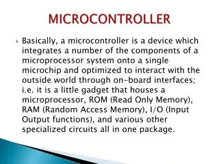
Microprocessors • What is a microprocessor? • Only a Central Processing Unit (CPU) • Has Address, Data and Control Buses • Note: By itself, it is totally useless.
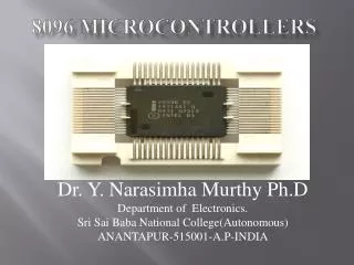
Microcontrollers • What is a microcontroller? • A processor • Parallel and serial digital I/O • Analog I/O • Counters and timers • Internal ROM and/or EPROM
Microcontrollers • What are microcontrollers used in? • Watches • Microwaves • Stereo Receivers • Some products that you might know: • NASA’s Sojourner Rover – 8-bit Intel 80C85 • Palm Vx handheld – 32-bit Motorola Dragonball EZ • Sonicare toothbrush – 8-bit Zilog Z8 • The Vendo V-MAX 720 Soda Machine – Motorola HC11
Microcontrollers Microcontrollers are a large market
Microcontrollers So what languages are they being programmed in? 1998-1999 1999-2000 Source: TRON Association Survey 1998/99 & 1999/2000
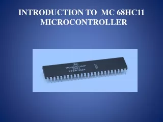
68HC11 • Motorola 68HC11E9 (features) • ROM (12KB), EEPROM (512B), RAM (512B) • Counter/Timer system • A/D converter • Parallel I/Os • Expansion bus • Serial communication
68HC11 68HC11E9 Architecture 12 KBYTES ROM 512 BYTES RAM
68HC11 CPU Memory Map of MC68HC11E9
68HC11 CPU 68HC11 Programmer’s Model
68HC11 CPU 68HC11 Programmer’s Model
D7 D6 D5 D4 D3 D2 D1 D0 0 1 1 0 0 1 1 1 68HC11 CPU Accumulator A and B ACCA or ACCB • ACCA or ACCB is a 8-bit general-purpose registers. • Stores temporary data from memory or I/O devices. • Stores result of allarithmetic and logic operations.
68HC11 CPU Accumulator A & B Example: • 1. LDAA $8000 ; loads contents of memory ; location $8000 into ACCA • 2. ADDA #$25 ; ACCA = ACCA + $25 • 3. STAA $9000 ; store result of ACCA into ; memory location $9000
68HC11 CPU 68HC11 Programmer’s Model
15 14 13 12 11 10 9 8 7 6 5 4 3 2 1 0 0 1 1 0 1 1 0 1 1 0 1 1 0 1 1 0 68HC11 CPU Accumulator D ACCD ACCB ACCA • ACCD represents Accumulator-D • ACCD = (ACCA + ACCB) to form a 16-bit register. • ACCA represents most significant byte (MSByte) • ACCB represents least significant byte (LSByte)
68HC11 CPU 68HC11 Programmer’s Model
15 14 13 12 11 10 9 8 7 6 5 4 3 2 1 0 0 1 1 0 1 1 0 1 1 0 1 1 0 1 1 0 68HC11 CPU Index Register X and Y IX or IY registers • Index register X and Y are two 16-bit registers. • Use in Index Addressing Mode. • Examples: • LDX #$1000 ;loads $1000 into IX • LDAA $10,X ;memory ($10+IX) content • ;load to ACCA.
68HC11 CPU 68HC11 Programmer’s Model
15 14 13 12 11 10 9 8 7 6 5 4 3 2 1 0 0 0 0 0 1 1 0 0 0 0 1 1 0 1 1 0 68HC11 CPU Stack Pointer (SP) SP Register • Stack occupied a small section in RAM memory. • Stack Pointer (SP) register: • a 16-bit register. • contains address of the stack. • Application of stack : • used in subroutine and interrupts operations • storing all the CPU registers contents.
68HC11 CPU 68HC11 Programmer’s Model
15 14 13 12 11 10 9 8 7 6 5 4 3 2 1 0 0 0 0 0 1 1 0 0 0 0 1 1 0 1 1 0 68HC11 CPU Program Counter (PC) Program Counter • Program Counter (PC) is a 16-bit register . • PC contains address of next instruction to be executed. • Example: • If PC = $0100, then; • CPU starts executing from memory location $0100 onwards.
68HC11 CPU 68HC11 Programmer’s Model
D7 D6 D5 D4 D3 D2 D1 D0 S X H I N Z V C 68HC11 CPU Condition Code Register (CCR) Condition Code Register (CCR) • CCR is an 8-bit register. • Bits 7 to 0 labeled as S X H I N Z V C respectively. • H, N, Z, V, C bits indicatestatus of last arithmetic or logic operation. • S, X, I bits indicate the masking bits.
7 6 5 4 3 2 1 0 S X H I N Z V C 68HC11 CPU CCR Explained Carry Overflow Zero Negative Stop Disable X-Interrupt Mask Half Carry I-Interrupt Mask
7 6 5 4 3 2 1 0 S X H I N Z V C 68HC11 CPU CCR Explained Carry Overflow Zero Negative Stop Disable X-Interrupt Mask Half Carry I-Interrupt Mask
68HC11 CPU N (Negative) bit • When the result of last arithmetic or logical operation is negative; then • N = “1” (MSB = “1”) • Whenever the result is positive; then • N = “0” (MSB = “0”) • Example • (1) LDAA #$7F ; N = “0” , msb = “0” (2) LDAB #$80 ; N = “1” , msb = “1”
7 6 5 4 3 2 1 0 S X H I N Z V C 68HC11 CPU CCR Explained Carry Overflow Zero Negative Stop Disable X-Interrupt Mask Half Carry I-Interrupt Mask
68HC11 CPU Z (Zero) bit • Z = “1” - result of last operation produces zero. • - accumulator content = $00 • Z = “0” - result of last operation greater than zero. • - accumulator content = $00 Example (1) LDAA #$00 ; Z = “1”, ACCA = 0 (2) LDAB #$01 ; Z = “0”, ACCB > 0
7 6 5 4 3 2 1 0 S X H I N Z V C 68HC11 CPU CCR Explained Carry Overflow Zero Negative Stop Disable X-Interrupt Mask Half Carry I-Interrupt Mask
68HC11 CPU C (Carry) bit • C =“1” - addition or subtraction produces a • carry or a borrow. • C =“0” - after addition or subtraction • no carry or no borrow. • *Note: C-bit also used in shift and rotate instructions. Example: LDAA #$80 ADDA #$90 ; C=“1” WAI ; bit-7 carries “1” to C-bit
7 6 5 4 3 2 1 0 S X H I N Z V C 68HC11 CPU CCR Explained Carry Overflow Zero Negative Stop Disable X-Interrupt Mask Half Carry I-Interrupt Mask
68HC11 CPU V (Overflow) bit • V =“1” - result is wrong,after an addition • or subtraction on 2’s complement • signed number caused an overflow • V =“0” - result is correct, after an addition • or subtraction on 2’s complement • signed number, no overflow
7 6 5 4 3 2 1 0 S X H I N Z V C 68HC11 CPU CCR Explained Carry Overflow Zero Negative Stop Disable X-Interrupt Mask Half Carry I-Interrupt Mask
68HC11 CPU H (Half-carry) bit • H =“1” - an 8-bit addition, produces a carry from bit-3 to bit-4. • H =“0” - an 8-bit addition, produces • no carry from bit-3 to bit-4. Example: LDAA #% 0011 1000 ADDA #% 0011 1010 ; H=“1” WAI ; (after adding) 1+1 produces a carry
7 6 5 4 3 2 1 0 S X H I N Z V C 68HC11 CPU CCR Explained Carry Overflow Zero Negative Stop Disable X-Interrupt Mask Half Carry I-Interrupt Mask
HC11 CPU Command Register I Interrupt Mask X XIRQ mask S Disable STOP instructions Note: Bits set by the user to tell the processor how to dothings
HC11 CPU Thank You