Download
1 / 35
350 likes | 573 Views
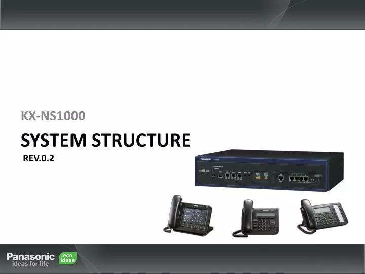
KX-NS1000. KX-NS1000. System Structure Rev.0.2. Introduction. This document explains System Outline and Specification of the KX-NS1000, and is composed of the following chapters. Chapter 1 System Outline Chapter 2 Configuration Chapter 3 Supported Card /Terminal

E N D
KX-NS1000 KX-NS1000 System Structure Rev.0.2
Introduction • This document explains System Outline and Specification of the KX-NS1000, and is composed of the following chapters. • Chapter 1 System Outline • Chapter 2 Configuration • Chapter 3 Supported Card /Terminal • Chapter 4 System Capacity • For further information about feature implementation and specifications, refer • to the "Installation Manual“.
Table of Contents • Chapter 1 System Outline • 1-1. KX-NS1000 System Overview • 1-2. System Connection Diagram • 1-3. Unified Messaging Overview • Chapter 2 Configuration • 2-1. Cabinet Configuration • 2-2. System configuration • Chapter 3 Supported Card /Terminal • 3-1. Terminal Compatibility • Chapter 4 System Capacity • 4-1. System Capacity • 4-2. Terminal Capacity • 4-3. Feature Capacity • 4-4. Email Client Capacity
Chapter 1 System Overview
1-1. KX-NS1000 System Overview Master Unit Slave Unit IP Network Up to 15 Units ・・・ • 1.Stand-alone System • - A single NS1000 can be used as a stand-alone system. • - To use the stand-alone system, you must install a DSP card on the PBX’s mother board, then install optional service cards into the physical slots and virtual slots. • 2.Networked System • A networked system can be realized by the following methods. • - One-look • - QSIG (required BRI /PRI card) • - H.323 (required V-IPGW card) * For detail, refer to the Networking Chapter.
1-2. System Connection Diagram IP/Legacy Trunks IP/Legacy Terminals Remote PC IP-PT Router Private IP Network NS1000 SIP-Phone IP-CS ITSP*1 Network PS IP-Softphone, CA*2 Client PC Unified Messaging *3 - Analogue Trunk - BRI Trunk - PRI Trunk PC PC PSTN*4 CTI Server SLT / FAX External Sensor /External Relay Device - NS1000 is based on Linux OS. Doorphone & Door Opener BGM/Music On Hold (MOH) *1 ITSP: Internet Telephony Service Provider *2 Communication Assistant *3 Built-into Main unit *4 Public Switched Telephone Network Amplifier / Pager/Speaker
1-3. Unified Messaging Overview • The Unified Messaging system is a new solution that adds unified messaging features such as voicemail, FAX and Email integration. • The following features are available: • Unified Messaging Feature • Voice mail (TVM Features) • Outlook add in Desktop Messaging • Fax Server • Automatic 2way Recording for Manager Feature • Presence (Absent Messaging) Feature • Unified Messaging feature is available with the Pre-installed SM card. Current New Storage memory card Built-in Main unit DPT I/F TVM TDE/NCP NS1000
Chapter 2 Configuration
2-1. Cabinet Configuration • Component location • The NS1000 (2U size) can be fitted to a 19-inch rack. (Depth is same as NCP Series) • Dimensions: 430mm (Width) × 88mm (Height) × 340mm (Depth) • Weight (when fully mounted): Under 4.5kg Front Side LED indicators MOH/EPG ports DPH Port (Option) Legacy Slot (Option) System mode SW USB port IP ports Back Side AC SW GROUND Serial port FAN AC cord clamp AC IN
2-2. System Configuration (1) • New Innovative system architecture • Provides the same level of PBX call control functionality as TDE/NCP system MPR Ver.4. NCP/TDE NS1000 System Administration + Networking PBX Call Control Features System Administration PBX Call Control Features Middleware - SIP protocol stack - Networking utilities - TCP /IP protocol stack (IPv4) Middleware - SIP protocol stack - Enhanced Panasonic-SIP OS (Linux) - Networking Utilities * - TCP /IP protocol stack (IPv4) OS (iTRON) CPU: SH-4 , 400MHz CPU: C1000 , 650MHz : NEW
2-2. System Configuration (2) • System Options DSP cards*1 DSP-S DSP-M *1 Each NS1000 (Master or Slave) must be fitted with a DSP card. DSP-L Storage Memory*2 Internal SM-S (Max 200hrs Rec) SM-M (Max 450hrs Rec) Mother board SM-L (Max 1000hrs Rec) Option cards External FAX DPH 1 Line cards LCOT2+SLC2 BRI4+SLC2 *2 The NS1000 has Storage Memory Pre-installed (SM-B), and by default allows 2 UM channels and 2 hours recording time. (Expandable to 24ch / 15hrs by Activation Key.) PRI30+SLC2
2-2. System Configuration (3) • Interface Cards (Line and Doorphone) • 4 types of Legacy Line cards are available for NS1000. • 1 type of Doorphone interface card is also available for NS1000. [Line Card ] [DPH1 Card ] • BRI4+SLC2 Card • LCOT2+SLC2 Card • PRI30+SLC2 Card NS1000 has 1 Free Slot for “Line card” and 1 Free Slot for “DPH1 card”.
2-2. System Configuration (4) • Interface Cards – Free Slot (Description)
2-2. System Configuration (5) • Optional Cards - Internal (Description)
2-2. System Configuration (6) • DSP Cards (Description) • Digital Signal Processor (DSP) Cards support VoIP calls, Conferencing, UM and DISA/OGM features on the NS1000 system. Up to Two DSP Cards can be fitted to each NS1000 unit, increasing the available DSP resource. At least 1 DSP Card must be fitted to each NS1000 so that the unit can operate. • There are 3 types of DSP card, each with different levels of DSP resource. • The more resource available, the more simultaneous features / calls can be maintained.
2-2. System Configuration (7) • Storage Memory Cards (SM) (Description) • The NS1000 unit comes pre-installed with 2ch UM and 2hrs of Voice Mail recording capability. This can be increased to 15hrs by installing the KX-NSU001 A/K. • The system VM recording capacity can be increased further by installing one of the optional SM cards.
2-2. System Configuration (8) • Virtual Cards • The NS1000 uses ‘virtual’ cards to support a range of IP based Trunks, Extensions, DECT Cell Stations and UM features. • Virtual cards features can be activated with the appropriate activation key. • Virtual Cards are configured via the Web-Based Maintenance Console. Virtual Card type Virtual Slot V-SIPGW16 V-SIPEXT32 V-IPCS4 V-IPUM12 V-IPGW16 V-IPEXT32 V-UTEXT32 Ethernet IP Telephony Service Other PBX IP-CS IP-PT SIP-MLT/SLT
2-2. System Configuration (9) • Virtual Cards (Specification)
2-2. System Configuration (10) • Activation Keys (A/K) • Activation Keys are required to activate the following features: • IP Trunk channel(H.323/SIP) • IP Telephone / Terminal capacity • Number of IP Telephones /Type of IP Telephones (IP softphone / IP-PTs / SIP Phones (UT series) / Other SIP Phones / IP Conferencing Phones) • Networking Features (One-Look, QSIG) • Unified Messaging Features (REC Time, 2-Way REC, Message Backup, UM Port capacity, UM/Email (IMAP + Voice / Fax messages) • Mobile Phone Features • CA related Feature (Thin Client, CSTA Mux, CA Pro, CA Supervisor, CA Console, CA Networking) • CTI Interface (Allows use of Third Party CTI Application) • Packages containing a combination of different A/K’s are also available to equip users with key UM and Mobility features easily.
2-2. System Configuration (11) • Activation Keys (A/K) – Cont.. • The NS1000 is equipped with Preinstalled Permanent Activation Keys These A/Ks exist within the PBX hardware and cannot be deleted and will not expire.
2-2. System Configuration (12) • Activation Keys (A/K) – Cont.. • In addition to the pre-installed permanent A/Ks, there is the option to activate ‘trial’ A/Ks which are valid for 60 days. These trial A/Ks will expire 60 days after activation. Trail A/Ks cannot be re-activated by initializing the PBX system. • Trial A/Ks (60 day expiry from activation)
Chapter 3 Supported Terminals
3-1. Terminal Compatibility (1) • New Range - SIP Telephone (UT Series) *1 UT113 : No backlit / UT123 : Backlit
3-1. Terminal Compatibility (2) • Telephone Terminals For compatible options (e.g., Add-on Key Module, USB Module, Headset), refer to the telephone’s manual.
3-1. Terminal Compatibility (3) • Other Terminals
Chapter 4 System Capacity
4-1. System Capacity (1) • Type and Maximum Number of Slots • The NS1000 supports the following type and number of slots.
4-1. System Capacity (2) • Maximum Optional Service Cards (1) • The following number of cards can be installed in the Physical Slots of the PBX. • Note • Any card that exceeds the capacity of the PBX will be ignored. • When the PBX starts up with an invalid configuration, some cards will be ignored.
4-1. System Capacity (3) • Maximum Optional Service Cards (2) • The following number of cards can be installed in the Physical Slots of the PBX. • Note • Any card that exceeds the capacity of the PBX will be ignored. • When the PBX starts up with an invalid configuration, some cards will be ignored.
4-1. System Capacity (4) • Maximum Optional Service Cards (3) • The following number of cards can be installed in the Virtual Slots of the PBX.
4-1. System Capacity (5) • Maximum Trunks and Extensions • The PBX supports the following number of trunks and extensions. *1 The maximum number of extension ports is 640 per PBX, and the maximum number of Unified Messaging ports is 24 per PBX. When 24 ports for Unified Messaging are fully activated on the Master unit, the maximum number of extension ports will be less than 640. One Unified Messaging port is equal to 10 extension ports. Therefore, when all Unified Messaging ports are activated, only up to 420 extensions are available. (The 2 Built-in UM ports are not counted in this calculation). This condition does not apply for Slave units or Stand-Alone units.
4-2. Terminal Capacity • Maximum Terminal Equipment • The following shows the number of each terminal equipment type supported by the PBX. *1 KX-NT300 series, and KX-NT265(v2.0).
4-3. Feature Capacity • Maximum Feature capacity • The following shows the maximum number of each feature supported by the PBX. NB: Total number of Login in Server Mode is 1022
4-4. Email Client Capacity • Outlook Integration with built-in Unified Messaging • The maximum number of IMAP clients using Outlook is 24 users per unit. • (Reason: Outlook keeps the IMAP session open, even though then user is idle.) *1) This limitation is not applied if the user can use Outlook in “Offline” mode. *2) Email which releases IMAP session when idle, such as Thunderbird, Lotus Notes etc. • Integration with POP • No limitation for users who receive voice data with an email attachment.