Download
1 / 63
1.46k likes | 2.94k Views
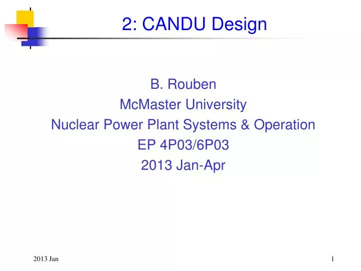
2: CANDU Design. B. Rouben McMaster University Nuclear Power Plant Systems & Operation EP 4P03/6P03 2013 Jan-Apr. Outline. The CANDU Evolution CANDU vs. PWR CANDU 6 Design. CANDU 9. 2000-20 10. Douglas Point. Cernavoda 1. Pickering A 1,2,3,4. Wolsong 2,3,4.

E N D
2: CANDU Design B. Rouben McMaster University Nuclear Power Plant Systems & Operation EP 4P03/6P03 2013 Jan-Apr
Outline • The CANDU Evolution • CANDU vs. PWR • CANDU 6 Design
CANDU 9 2000-2010 Douglas Point Cernavoda 1 Pickering A 1,2,3,4 Wolsong 2,3,4 CANDU Development Builds on a Strong History CANDU 9 1960-1970 Bruce A 1,2,3,4 Bruce B 1,2,3,4 Darlington 1,2,3,4 1945 1990-2000 1970-1990 Advanced CANDU Reactor and Beyond CANDU Evolution NPD Proto- types ZEEP Pickering B 1,2,3,4 G-2 Pt Lepreau Embalse Wolsong 1 Qinshan 1,2 CANDU 6
Spin out new technology to improve existing plants SCWR (CANDU X) Advanced CANDU Reactor ACR-1000 Current Generation CANDU 6 Evolution of CANDU Reactors
CANDU vs. PWR • Two different design philosophies • CANDU (CANada Deuterium Uranium) • Neutron economy • Natural uranium fuel • Separated heavy water (D2O) coolant and moderator • Distributed core (fuel channels) • Pressurized Water Reactor (PWR) • 235U enriched fuel • Combined light water coolant and moderator • Integrated core (pressure vessel)
CANDU and PWR Reactor Coolant Systems Comparison
CANDU-PWR Similarities/Differences • CANDU is a P(H)WR – Pressurized Heavy Water Reactor. • Key features of CANDU and PWR are the same or very similar: • UO2 fuel in long zirconium-clad elements • High-pressure reactor coolant • ‘Light bulb’ steam generator • Large concrete reactor containment structure • Turbine generator steam plant • Auxiliary systems (condenser water supply, pump-house, etc.) • Differences are primarily in the reactor core design.
Reactor-Core Design • CANDU • Natural uranium fuel • Heavy water coolant • Heavy water moderator • Separate coolant • and moderator • Pressure tubes • Small, simple fuel bundle • On-power fuelling • Boron reactivity control in moderator • PWR • Enriched 235U uranium fuel • Light water coolant • Light water moderator • Coolant and moderator • are same medium • Pressure vessel • Large, complex fuel assembly • Off-power fuelling • Boron reactivity control in coolant
CANDU-6 Plant Reactor Containment Building Turbine Building
Main CANDU Reactor Systems • Reactor Assembly • Fuel and Fuel Channel • Heat Transport System • Shutdown Cooling System • Pressure and Inventory Control System • Moderator System • Special Safety Systems
CANDU 6 7 1. Reactor face 2. Reactor coolant pump 3. Steam generator 4. Fuelling machine carriage 5. Moderator heat exchanger 6. Dousing water system 7. Dousing water tank 6 3 2 5 1 4
Reactor Assembly The reactor assembly contains the reactor core and the reactivity control devices. Major components of the reactor assembly are: • Calandria Vessel • End-Shields • Shield Tank • Fuel Channels • Reactivity Control Devices
Calandria Vessel • Low-pressure tank • Includes calandria tube and supports pressure tubes • Contains heavy water moderator • Contains reactivity control devices and shutdown systems • Embedded in light-water reactor vault (which provides radiation shielding) • Provides passive emergency heat sink in the event of a loss-of-coolant accident + loss-of-emergency cooling
Pressure-Tube Core Design • Sub-divided reactor coolant system, no large pressure vessel. • Cool moderator separated from hot coolant. • Zr-2.5%Nb pressure tubes constitute CANDU ‘pressure vessel’. • Individual pressure tubes are replaceable. • Modular component – allows scaling of reactor size • Zirconium alloy provides neutron economy. • Interstitial reactivity devices (between fuel channels). • Distributed core allows cooling to be maintained with failure of the small diameter reactor coolant system components (a pressure tube or feeder pipe).
CANDU Fuel • Natural uranium (~0.7% 235U). • High-density uranium oxide (UO2) fuel pellets in Zircaloy-4 cladding. • ‘Collapsible’ cladding under normal operating conditions. • Short (0.5 m) fuel elements arranged in cylindrical fuel bundles.
Heat-Transport System • Two independent circuits arranged in figure-of-8 configuration with pumps and steam generators. • System components sized to minimize D2O inventory. • All core-external circuit components located above core • Facilitates passive natural circulation thermosyphoning in the event of loss of pumped flow. • Prevents draining of the reactor by failure of piping. • Entire reactor coolant system pressure boundary inside containment.
CANDU-6 Heat-Transport System Design Reactor Coolant Parameters Outlet header pressure 10 MPa Outlet header temperature 310ºC Outlet header steam quality (max.) 4.0% Inlet header temperature 266ºC Secondary Side Conditions Steam pressure 4.7 MPa Steam quality <0.25% moisture Feedwater temperature 187ºC
STEAM GENERATOR Tube Bundles
Shutdown Cooling System • Long-term heat removal system. • 7% of full power heat removal capability at full pressure. • 1.2% of full power heat removal capability when depressurized. • Can connect to reactor coolant system at full pressure. • Heat sink when steam generators unavailable.
Moderator System • Low temperature (< 80oC), low pressure system. • Independent of reactor coolant system. • Normal heat removal is ~4% of full power. • Potential heat sink if Emergency Core Cooling is unavailable during a Loss-of-Coolant Accident (LOCA). • Contains shutdown systems located outside of high-pressure heat transport system. • Low temperature moderator cannot add to pressure of containment (add energy) during a LOCA.
On-Power Refuelling • Regular, routine fuel bundle insertion (fresh fuel) and removal (spent fuel) on power. • Maintains a constant power shape in the core. • Maintains an equilibrium fuel burnup (steady state source term for potential releases). • Shutdown system effectiveness does not change during a fueling cycle. • Permits on-power removal of failed fuel. • Keeps radioactive contamination in coolant system low. • Minimizes dose to workers.
CANDU 6 Reactor(700-MWeClass) Guide Tubes for Reactivity Devices and In-Core Flux Detectors Ion Chambers
Long-Term Reactivity Control For long-term maintenance of reactivity: Refuellingis required because reactivity eventually decreases as fuel is irradiated: fission products accumulate and total fissile content decreases. In CANDU 6, average refuelling rate ~ 2 channels per Full-Power Day (FPD), using the 8-bundle-shift refuelling scheme (8 new bundles pushed in channel, 8 irradiated bundles pushed out). 4-bundle-shift and 10-bundle-shift refuelling schemes have also been used in other CANDUs. Selection of channels is the job of the station physicist.
Fuelling machines at both ends of the reactor remove spent fuel, insert new fuel
Reactor Regulating System The reactivity devices used for control purposes by the Reactor Regulating System (RRS) in the standard CANDU-6 design are the following: 14 liquid-zone-control compartments (H2O filled) 21 adjuster rods 4 mechanical control absorbers moderator poison.
CANDU Reactivity Devices All reactivity devices are located or introduced into guide tubes permanently positioned in the low‑pressure moderator environment. These guide tubes are located interstitially between rows of calandria tubes (see next Figure). Maximum positive reactivity insertion rate achievable by driving all control devices together is about 0.35 mk/s, well within the design capability of the shutdown systems.
Special Safety Systems There are in addition two spatially, logically, and functionally separate special shutdown systems (SDS): SDS-1, consisting of 28 cadmium shutoff rods which fall into the core from above SDS-2, consisting of high-pressure poison injection into the moderator through 6 horizontally oriented nozzles. Each shutdown system can insert > 50 mk of negative reactivity in approximately 1 s. Next Figuresummarizes the reactivity worths and reactivity-insertion rates of the various CANDU-6 reactivity devices.
REACTIVITY WORTHS OF CANDU REACTIVITY DEVICES Function Device Total Reactivity Worth (mk) Maximum Reactivity Rate (mk/s) Control 14 Zone Controllers 7 0.14 Control 21 Adjusters 15 0.10 Control 4 Mechanical Control Absorbers 10 0.075(driving) - 3.5 (dropping) Control Moderator Poison — -0.01 (extracting) Safety 28 Shutoff Units -80 -50 Safety 6 Poison-Injection Nozzles >-300 -50
Liquid Zone Controllers For fine control of reactivity: 14 zone-control compartments, containing variable amounts of light water (H2O used as absorber!) The water fills are manipulated: • all in same direction, • to keep reactor critical for steady operation, or • to provide small positive or negative reactivity to increase or decrease power in a controlled manner • differentially, to shape3-d power distribution towards desired reference shape
For fast power reduction: 4 mechanical absorbers (MCA), tubes of cadmium sandwiched in stainless steel – physically same as shutoff rods. The MCAs are normally parked fully outside the core under steady‑state reactor operation. They are moved into the core only for rapid reduction of reactor power, at a rate or over a range that cannot be accomplished by filling the liquid zone‑control system at the maximum possible rate. Can be driven in pairs, or all four dropped in by gravity following release of an electromagnetic clutch. Mechanical Control Absorbers