Download
1 / 26
260 likes | 387 Views
Elec467 Power Machines & Transformers. Electric Machines by Hubert, Chapter 5 Topics : Induction machines classifications, performance, applications, and operation. Torque-speed.

E N D
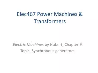
Elec467 Power Machines & Transformers Electric Machines by Hubert, Chapter 5 Topics: Induction machines classifications, performance, applications, and operation.
Torque-speed Torque-speed characteristics of basic NEMA designs for squirrel-cage induction motors. In this chapter we will learn what effect the rotor resistance has on these designs.
Rotor designs The way the rotor is physically designed has a direct effect on the torque-speed plot because it guides the flux field.
Induction motor equivalent circuit The actual parameters of a motor are display above and labeled. The value for each parameter are considered per phase.
Modification to text Delete the 2nd equal sign in the first four equations on page 178 of the text. Students are reminded of the role the turns ratio plays in referring the components Rr and XBR to the stator side of the equation and the inverse relationship the turns ratio has with the voltage and current.
Induction motor equivalent circuit Rr, X1 are changed into R2, X2 by application of the turns ratio squared, a2, and I2 is Ir divided by a and E2 is EBR multiplied by a.
Equivalent circuit definitions for Fig. 5-4 R1 = RS per Fig. 5-4 In these definitions the operative word is “per phase”. The equivalent circuit represents 1 phase of the three thus the power isn’t determined by the power in one phase but by multiplying the power for one phase by 3. Also, voltage and current measurements are line values that have to be changed to phase values. Since we assume a wye-connected motor/generator and we use one in the lab then VL=√3 VØ and IL = IØ.
Formulas from Fig. 5-4 from page 179 of the text
Locked rotor Equation 5-3. By rearranging circuit of Fig. 5-4 and emphasizing that I2 and V are vectors, their magnitude can be taken… and TD derived. After some more math you can find the value of R2 the rotor resistor so that TD occurs at block rotor: (5-5) (5-8)
More math Since Thus The observation made from all this math: Changing the value of rotor resistance will change the slip at which TD,max occurs, but will not change the value of TD,max This is the means and methods for the different motor designs seen in the first slide. The substitutions above are valid for normal running of an induction motor. Normal running is defined as operating between no load and 15% overload with rated voltage and rated frequency. The slip under these conditions is very small <0.03. See Figure 5-7 on the next slide for the straight-line approximation.
Rotor current & Torque Fig. 5-7
Torque-slip curves for wound-rotor The rotor rheostat setting changes the slip that TD,max occurs. For example, maximum resistance generates curve 5. Minimum resistance puts you on curve 1. For no-load this would mean the intercept of curve 5 at s=1 gives 140% torque over rated load; the motor would start to turn if the load doesn’t exceed 140% of rated load. If you had a rated load of 100% then the motor increase speed up to s=.7 Thus for any given constant load, such as 100% rated load (in bold on figure) changing the rheostat changes the slip which in effect the shaft rotation or speed the motor is rotating. The formula nr =sns is a method for variable speed control of motors. Fig. 5-9
Derating Imbalances in the 3Ø line voltage overheats motors. Motors should be run at a lower horsepower using the factors determined from the chart for Figure 5-13 Large motors >50 hp are adversely affected by starts. There are limits on lifetime starts with waiting periods between starts When a motor is stopped by switching off the line voltage, the rotor continues to turn sending voltage back out thru the stators. Out-of-phase starts can create in-rush current of 200% rated values.
DC tests This test is used to determine R1 First find RDC from voltage & current 2nd select the type of winding
Blocked Rotor Test Power, voltage and current are taken from measurements while the rotor is blocked. IBR is the average of the two amp meter readings. This test determines X1 , X2 and R2 Calculate the values solving the formulas below left to right, top to bottom: Equivalent circuit assumptions IO<<IR Assign values to X1, X2 according to the Table 5.10, if motor type unknown assume X1 = X2
No-load test This test determines XM and combined core, friction and windage losses Equivalent circuit assumptions To match up lab symbols to text: XBR = Xeq RBR=Req and PXX = sum of watt meters give 3Ø power Calculate 3Ø apparent power using line voltage Step 1 Reactive power for all 3 phases Step 2 Calculate 1-Ø reactive power Step 3 Similarly using an approximation of the magnitude IM>>Ife as 10: Step 4
Two additional formulas Use as an approximation of Rfe: Use the following equation for Pf,w and Pstray:
Generation overview In the above power generating system, assume the line voltage is driving the motor at near synchronous rotor speed ns with the turbine steam valve turned off. If the steam was let in, the turbine would turn faster causing nr to be larger than ns thus creating a negative slip. When this occurs the flux field at the gap reverses and the motor begins providing current to the line.
Transition plots motoring to generator The above graphs show the motor action that we’re familiar with and the generator action which appear much like an inverted mirror image of the motor side. The limits of operation in either case are between the two extreme values: Breakdown and Pushover.
Overlay current Graph (b) shows the overlay of the torque curve with the expected line current. The current’s value doesn’t really go negative as one would expect with a DC current; because its AC, the current is constantly reversing. The exciting current exists in the motor when generating and is supplied by the line current.
Self-Excited Generators When an induction motor is run as a generator, it is called an induction generator. Induction generators can be driven by a diesel or gasoline motor and can be set up in remote locations (like your backyard). While AC input voltage is necessary for the exciting circuit to work, enough voltage can be created without connecting the generator to the electrical grid. This is accomplished by connecting 3 capacitors across the input terminal of the motor which are essentially the output terminals of the generator. Residue magnetism in the rotor creates a small voltage output and the capacitors build up the voltage over time to provide the exciting current, IO, to the stators. When this occurs, the generator provides power on its output terminals.
Stopping the motor • A simple way to stop the motor is to simply disconnect the motor from the AC line and let it coast to a stop. In order to lock the rotor, it requires a mechanical application. • Another method to stop the rotor quickly is to interchange two of the AC line supply before its comes to a rest. This reverses the motor’s electric field causing the motor to attempt to rotate in the opposite direction. • This is called PLUGGING. It will create slip values greater than one because nr becomes negative after the rotor comes to a rest as the rotor begins rotating in the opposite direction. • Torque values and current surges created during this operation can become excessive and destroy the motor unless it was designed for this operation. See Figure 5-9 for the plot of torque values greater than one.
Dynamic Braking Dynamic braking is the slowing down of a machine by connecting the motor to a braking circuit. There are two types of braking circuits: DC injection or capacitive braking. Seen above is DC injection that operates by opening the contactor on the input AC lines and closing thru the contactors from the braking circuit that is rectifying the AC signal with diodes. Connecting the motor to a DC circuit causes the stators to become permanent magnets and replaces the rotating field with a static field that will also hold the rotor in place at rest.