Download
1 / 28
280 likes | 423 Views
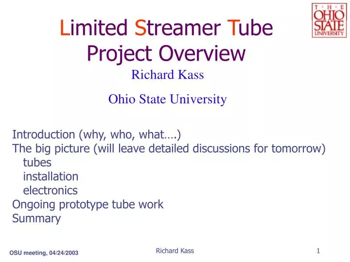
L imited S treamer T ube Project Overview. Richard Kass Ohio State University. Introduction (why, who, what….) The big picture (will leave detailed discussions for tomorrow) tubes installation electronics Ongoing prototype tube work Summary. Dec. 2002. Key LST Project Goals.

E N D
Limited Streamer TubeProject Overview Richard Kass Ohio State University Introduction (why, who, what….) The big picture (will leave detailed discussions for tomorrow) tubes installation electronics Ongoing prototype tube work Summary Richard Kass
Dec. 2002 Richard Kass
Key LST Project Goals Good efficiency to detect muons and KL’s must fit in the present barrel structure thickness of detector limited to “22mm” Long Term Reliability last until the end of BaBar Installable during summer shutdowns 1/3 in 2004 2/3 in 2005 Richard Kass
The Initial LST Team* *As of Feb BaBar Meeting M. Andreotti, D. Bettoni, R. Calabrese, V. Carassiti, A. Cotta Ramusino, G. Cibinetto, E. Luppi, M. Negrini, L. Piemontese INFN Ferrara T. Allmendinger, K.K. Gan, K.Honscheid, H. Kagan, R. Kass, A. Rahimi, C. Rush, Q. Wong, M. Zoeller Ohio State University C. Fanin, M. Morandin, M. Posocco, M. Rotondo, R. Stroili, C. Voci INFN Padova M. Loveterre, E Robutti, S Passaggio, S Capra, C Patrignani, S Minutoli INFN Genova G Piredda, C. Voena, F. Ferroni, S. Morganti, L. Cavoto INFN Roma R. Baldini, A. Calcaterra, P. Patteri, A Zallo, U. Denni, INFN Frascati L. Cavoto, R. Fernholz, C. Lu, J. Olsen, W. Sands, A.J.S. Smith Princeton University We welcome new groups! Richard Kass
LST Building Blocks Tubes: The basic building block Each tube is ~2´10´375 cm A tube forms the gas volume (IsoB/Ar/CO2) Anode wires are ganged together in a tube 16 wires/tube double layer small cells 8 wires/tube single large cell Resistive graphite coating on inner walls Do not readout anodes, use cathode strips ~2000 tubes in system Modules: Groups of tubes Tubes (e.g. 6) glued together form a module ~400 modules in system Richard Kass
Small Cell Tube Design Single layer of 9x9 mm cells limited to e ~90% by geometry FNeed 2 layers of wires to obtain efficiency > 95% Questions of long term reliability of 9 x 9 cells Propose double-layer of wires in small cells (9x8mm) Readout of x and y coordinates from outside strips Will not readout the anode wires Thickness of double layers ~23mm will use 9x9’s where gap is only 22 mm Richard Kass
Double Layer Design Richard Kass
Large Cell Tube Design Single-layer of wires in a large cell (15x17 mm) Readout of x and y coordinates from outside strips Will not readout the anode wires 15x17mm cells Reliability expected to be much higher for large cell less sensitive to mechanical imperfections Failure rate of MACRO tubes 0.1% in ten years ZEUS high initial mortality, 5%, then 2 % in 7 years Possibility to power HV on each or only 2 cells Richard Kass
The LST building blocks Base Design: z-strips 38.5 mm wide 96/layer, 6912 total -strips 42.5 mm wide 2 strips/tube 4074 total 10986 channels of electronics Richard Kass
LST DETECTOR LAYOUT Exploded view of the composite detector module. f strip readout board shown Richard Kass
1: PET 190m with copper lamination machined in strips of width W and separation gap G; G = 2 mm, W = 36mm for the Z strips, W = 36mm or 40mm for the f strips according to the version of LST. 2,3: PET 250 m 4: PET 50 m with solid copper lamination 4 3 ~ 0.9mm 2 1 2 mm W G E Composite readout strip plane Richard Kass
IFR FORWARD Z IFR BACKWARD signal connectors Installation of the Z-strip plane decoupled from the modules Zstrip readout plane is installed before the modules corner pieces are removed Zstrip connectors located at the backward end of the Z plane will not block insertion of the modules from forward end of the IFR z plane fabricated from 3 boards Richard Kass
Installation Z-Strip Plane Inserted into Gap before modules THE Z-STRIP PLANE SLIDES INTO THE GAP A TOOLING FOR HOLDING AND MOVING THE FOIL IS NEEDED Richard Kass
Modules Are Inserted Into Gap After Z-Stripnumber of tubes/modules/gap varies… Installation Richard Kass
An Individual Module Can Be Extracted From the Detector De-Installation Unlike the Present RPC System Richard Kass
Electronics Front End Electronics (Ferrara, Genova, Ohio State) Conceptual Design for Front End complete High Voltage (Ohio State, Padova) Conceptual design for OSU system complete Evaluating CAEN system recycle high voltage system from LVD Data acquisition system Use present RPC system Richard Kass
Front End card: block diagram Richard Kass
Layout of the readout crate Richard Kass
First OSU HV Prototype (5 ch) 15 V In HV Op-Amp Floating 5V Supply Current Monitor Outputs Current Monitor Protection 0-5 kV Out 6kV Dc/Dc Richard Kass
Tube Prototypes Four different types of tubes are under study 1) pre-prototype double layer tubes (9x9=>9x8 mm) 2) “standard” cells: 9 x 9 mm tubes 3) “small” cells: 9x8 mm double layer tubes 4) “large” cells: 15x17 mm single layer tubes baseline Very detailed studies of each tube geometry: voltage plateau mechanical stability signal quality shielding issues Richard Kass
Configuration Efficiency LST Prototypes Both side ON 96.5% 1 side ON – same side 92.8% 1 side ON – opposite side 91.2% The first double-layer prototype! First prototype (two 9x8 profiles) was built in order to test the readout scheme To do this old 9x9 profiles were machined down to 9x8 mm Readout scheme successfully tested Efficiency measured, about 96% Voltage Plateau narrower than expected L Prototypes have been opened up and examined Problem traced to inadequate Q/C, rough edges in machined profiles (actual tubes will be extruded) Richard Kass
“standard” 9x9 mm tubes LST Protypes Ordered 20 standard 9x9 tubes re-establish production quality 10 with Au-coated wires 10 with Ag-coated wires Plateau measurements in progress, first results are very good silver wire similar good results for gold wire Richard Kass
LST Prototypes “small” cells Prototype pre-production of 9x8 mm cells two profiles in a single cover Order for dies and all components placed Expect the tubes early May Goal: Have these tubes tested by Elba meeting Richard Kass
LST Prototypes large-cell single layer prototype Dies ordered for 15 x 17 mm cell Graphite coating machine modifications built This is not standard technology for Pol.Hi.Tech Fabricate parts necessary to complete prototype designed and ordered Expect to be able to test prototypes in early June Richard Kass
Pol.Hi.Tech. will assemble and test tubes Tube Construction and Assembly Tubes will be manufactured and assembled in Italy Focus on quality control Inspection of Comb Shape Profiles Inspection of graphite coating Surface resistivity monitor wire stringing proceedure Inspection of end caps Test for gas leaks HV conditioning Long Range Test and Plateau measurement Add Additional Checks as necessary Richard Kass
Module Assembly Tubes will be glued together to make modules Assembly sites at Princeton and OSU Focus on quality control Inspection of Shipping Boxes Tube Resisitance and Capacitance Measurement Leak Test?? Burn in Procedure (~1 week) Signal Shape Test Plateau Curve (>300V) Tube Efficiency Scan Test with Radioactive Source Inspect f strips Module burn in test (~1 weeks) Add Additional Checks as necessary Richard Kass
What Do We Have To Do? Pre-production • Refine Cost estimate, WBS for IFC • Design cables and understand compatibility with RPC FEC • Prototyping • Test present prototypes • Visit PolHITech to discuss manufacture procedures • Aging of PVC • Double and/or single layer • Decide geometries to order • F strip design • Z strip design • Obtain standard 9x9 with high resistivity • Make drawings for dies, mandrils • Understand finances for prototype costs • Order prototypes • Test prototypes • Order tubes Richard Kass
production What Do We Have To Do? z strip construction, QC F strip construction, QC HV System HV Distribution Monitoring, Controls (Gas System, HV, environment, etc) Simulation Monitoring electronics Cabling Gas system design Gas system fabrication Ship stuff to SLAC Receive, test, store modules at SLAC Installation fixtures Installation plan and procedure Plan for replacements, repairs Design set Q/A up Follow construction at Polytech Test tubes at PolHi Tech Ship to OSU and Princeton FEC design FEC design review Test FEC prototype FEC production Crates FEC testing FEC Q/A Design and fabricate Assembly Fixtures Material Handling, Equipment, and procedures Receive and test tubes at assembly sites Assemble modules Full system test in US Ship to SLAC Data Base setup Many important tasks still not covered! FOpportunities for new groups. Richard Kass