Download
1 / 21
210 likes | 403 Views
MECO Production Target Developments. James L. Popp University of California, Irvine NuFact ’ 03 Columbia, June, 2003. Institute for Nuclear Research, Moscow V. M. Lobashev, V. Matushka New York University

E N D
MECO Production Target Developments James L. Popp University of California, Irvine NuFact’03 Columbia, June, 2003
Institute for Nuclear Research, Moscow V. M. Lobashev, V. Matushka New York University R. M. Djilkibaev, A. Mincer, P. Nemethy, J. Sculli, A.N. Toropin Osaka University M. Aoki, Y. Kuno, A. Sato University of Pennsylvania W. Wales Syracuse University R. Holmes, P. Souder College of William and Mary M. Eckhause, J. Kane, R. Welsh Boston University J. Miller, B. L. Roberts, O. Rind Brookhaven National Laboratory K. Brown, M. Brennan, L. Jia, W. Marciano, W. Morse, Y. Semertzidis, P. Yamin University of California, Irvine M. Hebert, T. J. Liu, W. Molzon, J. Popp, V. Tumakov University of Houston E. V. Hungerford, K. A. Lan, L. S. Pinsky, J. Wilson University of Massachusetts, Amherst K. Kumar MECO Collaboration J.L.Popp, UCI MECO Production Target
The Superconducting Solenoids Muon Beam 1 T 1 T Calorimeter 2 T Straw Tracker Stopping Target Foils Proton Beam 2.5 T 5 T p Production Target MECO Muon Beam Line at AGS • Goal: 1011 stopped m- / sec • 1000-fold increase in m beam intensity over existing facilities High-intensity proton beam and high-density target Target, cooling, & support: compact to minimize p absorption Axially-graded 5 T solenoid field very effective at p collection J.L.Popp, UCI MECO Production Target
Target: High density cylinder, L = 16 cm, R = 3-4 mm 4.0*1013 7.5 GeV protons / sec from AGS Slow extraction, 0.5 s spill, 1.0 s AGS cycle time 2 RF buckets filled: 30 ns pulses, 1350 ns apart Total on-spill power deposition: 7500 - 9500 W On-peak energy deposition distribution: V. Tumakov Target Heating J.L.Popp, UCI MECO Production Target
Production Target Cooling • Radiation • minimal material in production region to reabsorb p’s • significant engineering difficulties to overcome • high operating temperature, Toperation = 2145 – 3000 K - high thermal stresses - target evaporation - little hope of raising production rate beyond current goals • low-density materials: manageable stresses; but extended complex shapes, difficult to support & can lead to excessive pion reabsorption • Forced Convection w/ water as coolant • low operating temperature, Toperation < Tboil - water - negligible thermal stresses - hope for achieving greater sensitivity • minor impact on MECO sensitivity: cooling system absorbs p’s • modest engineering difficulties handling coolant (water activation) J.L.Popp, UCI MECO Production Target
Target Titanium Water Production Target Physics Simulations Simulations of design parameters with GEANT3 indicate that both production target cooling methods can meet MECO physics requirements GEANT Simulations of Muon Yield Small water channel & thin containment tube costs 5% muon yield Inlet & outlet pipes and target radius should be reoptimized Tungsten target R = 3 mm, L = 16 cm Radiation-cooled All with 3 mm OD inlet/outlet pipes Large inlet/outlet UCI: A. Arjad, W.Molzon, M.Hebert, V.Tumakov, J.Popp J.L.Popp, UCI MECO Production Target
Radiation Cooling: Lumped Analysis of Heating Cycles • Tungsten cylinder • R = 4 mm • L = 16 cm • Long time limit: • W: Tmelting = 3683 K J.L.Popp, UCI MECO Production Target
Radiation Cooling: On-Spill Temperature & Von Mises Stress Temperature • Tungsten cylinder, symmetry ¼ • L = 16.0 cm, R = 4 mm • Power distribution: gaussian • Thermal dependence: Properties W beamdirection Von Mises stress Region of maximum Von Mises stress, sYield = 20 Mpa or less Dividing up target into 0.1 cm slices, slotting & to axis, spacing by 0.8 cm gives stability, but target size is unacceptable C. Pai, BNL J.L.Popp, UCI MECO Production Target
inlet outlet highest temperature location beamdirection Current Water-Cooled Design • Pt or Au cylinder: L = 16.0 cm, R = 3.0 mm • Ti inlet & outlet pipes: 25 cm long, ID = 2.1 mm, OD = 3.2 mm • Annular coolant channel: h = 0.3 mm • Tapered inlet end reduces pressure drop across target • Water containment shell: 0.5 mm wall thickness • In MECO: Cut-away side view J.L.Popp, UCI MECO Production Target
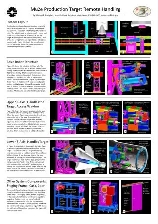
Target Installed in Production Solenoid • 0.5” service pipes • Slot in heat shield: - guide - positioning • Simple installation: - robotic manipulation - no rotations need - total of 1 vertical & 2 horizontal translations required • Opening in heat shield for beam entrance • Target rotated slightly off-axis to be optimally oriented for the beam J.L.Popp, UCI MECO Production Target
Target Fully Installed: Cut-Away Wide View of Production Solenoid Target Beam entrance Solenoid coil packs W.Molzon, J.Popp, M.Hebert, B.Christensen J.L.Popp, UCI MECO Production Target
Water Cooling: Lumped Analysis of Heating Cycles Simple calculations and hydo code indicate large heat transfer coefficient Characteristic response time is of order AGS cycle time Target may reach steady state T on each cycle Time-dependent turbulent hydrodynamic simulations required to fully characterize the time behavior and more precisely the maximum coolant temperatures: CFDesign – suitable computational tool J.L.Popp, UCI MECO Production Target
15.5 m/s Turbulent Flow Axial Velocity, V(r,z) Coolant containment wall Target surface 0.0 m/s r z Turbulent Flow in Annular Water Channel • Worst case: steady state, 9500 W • Inlet water conditions • temperature = 20 C • flow rate = 1.0 gpm • velocity = 10.6 m/s at inlet • Flow channel • length = 16.0 cm • radius = 3.0 mm • gap = 0.3 mm • Design parameters • target pressure drop = 127 psi • inlet pressure = 207 psi • outlet pressure = 80 psi • max. local water temp = 71 C • max. target temp (Au) = 124 C (core) • mean discharge temp = 56 C • stopped muon yield > 95% of rad. cooled J.L.Popp, UCI MECO Production Target
Coolant containment wall Target surface Target surface Axial position - z r z Steady State Temperature DistributionWater-cooled Target 397.6 K Water gap, 0.3 mm Zoom below 47 C Titanium containment wall Target core 293.1 K • Diffusion dominated heat transfer layer: 10-20 mm • Fully developed turbulence in about 7 gap thickness • Re: 15000 - 30000 J.L.Popp, UCI MECO Production Target
Target Center Target/Water Interface 397 K Water Channel Center Titanium Tube Inner Surface Water Inlet Target Core 293 K Target and Water Temperature Under Turbulent Conditions Heat transfer calculations for turbulent flow conditions demonstrate feasibility of the cooling scheme • Turbulence calculation - unstable flow - - local fluctuations - - solutions to N-S eqs - time averaged, Dt - UCI: J.Carmona, R.Rangel, J.LaRue, J.Popp, W.Molzon J.L.Popp, UCI MECO Production Target
Target Cooling Test Stand Diagram • Control: target geometry & flow rate • Monitor: temperature & pressure: - target inlet & outlet - reservoir - target (not shown) • Temperature probes: - thermistors - thermocouple • Measurements of interest in heating tests: - power deposition in target - heat transfer coefficients target heat exchanger - target surface temperature - response times for power cycling J.L.Popp, UCI MECO Production Target
Target Prototype Tests Water cooling effectiveness is being demonstrated via prototypes • Pressure drop vs. flow rate tests completed • First induction heating test completed, next test June 2003 Comparison of Prototype Data with HD Simulations Two right-turns Tapered ends Actual pressure drop is lower than simulations predict UCI: J.Popp, B.Christensen, C.Chen, W.Molzon J.L.Popp, UCI MECO Production Target
Induction Heating Principle: Excite eddy currents which oppose changing magnetic flux, to obtain heating via Apply AC current to coil wrapped around work piece (e.g., solid rod, billet,…): H0 = surface magnetic field intensity Solid cylinder: • Ameritherm, Inc.; http://www.ameritherm.com • Induction Heat Treet, Co.; Huntington Beach, CA - 20 kW, 175 kHz - 30 kW, 10 kHz • Example: Tensile test for metals at extreme temperatures J.L.Popp, UCI MECO Production Target
Measured Power Deposition • Solid rod: - R = 3.0 mm, L = 16.0 cm - Carpenter Technologies: High Permeability Alloy 49, 50/50 Fe/Ni • Measured power deposited: - reservoir temperature rise - (outlet – inlet) temperature • Approximately same result: 1450 W • 264 W per K / unit discharge (gpm) • Increase power deposition: - more turns per meter (coil w/ two close-packed layers) - reduce OD water containment shell - consider using higher-power unit • Induction coil: - 152 turns/m - L = 23.6 cm, R = 3.8 cm - copper tubing: OD = 0.635 cm • Power supply - Lepel 20kW unit - f = 175 kHz J.L.Popp, UCI MECO Production Target
Measured Target Surface Temperature • Annular water gap, h = 0.4 mm • Flow rate = 1.0 gpm • DP = 125 psi • Probe near max surface T position: - 1.9 cm in from outlet end - > 0.5 mm below surface • Ttarget- Tinlet = 21.0 C • Scaled to MECO: PMECO = 7500 W, (Ttarget- Tinlet)PMECO/Ptest = 108 C • Good approx.: Tsurface = Tinlet + 108 C • To maintain non-boiling condition - raise outlet pressure - chill inlet water - increase discharge rate • Skin depth: d = 0.018 mm - f = 175 kHz - relative permeability m/m0 = 2050 • Ttarget probe : - probe radial position not critical - Tcore- Tsurface << Ttarget probe J.L.Popp, UCI MECO Production Target
What next ? • Opera calculations: redesign coil for greater power - two layers of coil windings - reduce OD of copper tubing, etc. - evaluate using 20 vs 30 kW unit (higher current & lower freq) • 2nd heating test in June 2003 - improved sensor operation - higher power deposition - gap size 0.4 mm, run at higher flow rate - gap size 0.3 mm, run at various flow rates - more precise positioning for target surface temperature probe - characterize response time of target • Opera calculations: design coil for MECO longitudinal heating profile • Redesign water containment shell to improve pressure drop • More heating tests in July 2003 J.L.Popp, UCI MECO Production Target