Download
1 / 6
70 likes | 237 Views
A(s). +. . compensator. plant. R(s). M(s). C(s). G c ( s ). G p ( s ). sensor. H(s). R(s). E(s). C(s). +. H -1. H -1. G c G p. . 5. CONTROL SYSTEM CHARACTERISTIC. Stability Sensitivity Disturbance rejection . Steady state accuracy Transient response

E N D
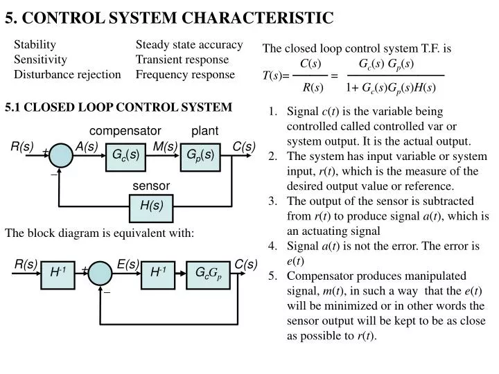
A(s) + compensator plant R(s) M(s) C(s) Gc(s) Gp(s) sensor H(s) R(s) E(s) C(s) + H-1 H-1 GcGp 5. CONTROL SYSTEM CHARACTERISTIC Stability Sensitivity Disturbance rejection Steady state accuracy Transient response Frequency response The closed loop control system T.F. is C(s) Gc(s) Gp(s) T(s)= ──── = ─────────── R(s) 1+ Gc(s)Gp(s)H(s) 5.1 CLOSED LOOP CONTROL SYSTEM • Signal c(t) is the variable being controlled called controlled var or system output. It is the actual output. • The system has input variable or system input, r(t), which is the measure of the desired output value or reference. • The output of the sensor is subtracted from r(t) to produce signal a(t), which is an actuating signal • Signal a(t) is not the error. The error is e(t) • Compensator produces manipulated signal, m(t), in such a way that the e(t) will be minimized or in other words the sensor output will be kept to be as close as possible to r(t). The block diagram is equivalent with:
5.2 STABILITY A LTI system is BIBO stable provided that all poles of the TF lie in the LHP. Example a system with TF The poles of this TF can be found by solving the equation obtained by equating the denominator of (1) to zero, that is solving 1+ Gc(s)Gp(s)H(s) = 0 (2) Equation 2 is called the characteristic equation (CE). The denominator 1+ Gc(s)Gp(s)H(s) can be expressed as a polynomial this polynomial is called the characteristic polynomial and equals to in the Mason gain formula. Thus the characteristic eq. can be expressed as (s) = 0 The CE can also be obtained from the state variable model is stable because its poles p1= 1 and p2= 2 lie in the left-half of the s plane. A system with TF is unstable because one of its poles p2= 3 lie in the right-half s plane The closed loop control system T.F. is C(s) Gc(s) Gp(s) T(s)= ——— = ———————(1) R(s) 1+ Gc(s)Gp(s)H(s)
5.2 STABILITY Recall that the state model of a system is The T.F. is The denominator of this T.F is det (sI-A), thus the CE is det (sI-A)=0 System is stable if all the roots of this equation is ont the LHP • In summary the CE can be expressed in 3 ways; • 1+ Gc(s)Gp(s)H(s) = 0 • (s) = 0 • det (sI-A)=0 • and the stability is found by determining the location of its roots
(1) (3) (2) 5.3 SENSITIVITY Sensitivity, S, is a measure of changes in system characteristic due to changes in parameters. Sensitivity is measured as Consider the sensitivity of system to plant T.F GP(s). From (2), • where • T(s) is the change in T.F T(s), • b is the change in parameter b. By definition sensitivity function is where GL=GcGpH. It is often that (3) be evaluated as a function of frequency Some useful sensitivity function. The closed loop control system T.F. is GcGpH evaluated at a specified frequency is called the loop gain Gc(s) Gp(s) T(s)= ———————— 1+ Gc(s)Gp(s)H(s) Setting GClarge will reduce the sensitivity.
compensator plant R(s) C(s) + KP sensor (4) H 5.3 SENSITIVITY Now consider the sensitivity of system to sensor T.F H(s), again from (2), Example: Setting GClarge will increase the sensitivity. We see that the system can not be insensitive to both plant and sensor. To solve this problem we have to choose the high quality stable sensor, since we may not able to do this for the plant. We have consider the sensitivity to GPor H. However GP or H will vary to due to the variation of some parameters in GP or H. The sensitivity of T(s) to parameter b in H can be expressed as: GP(s) = K/(s+0.1) where K has nominal value 5,H = 0.05. We will find sensitivity of T(s) with respect to K the numerator of GP(s). T(s) can be found to be
5.3 SENSITIVITY The sensitivity about the nominal value of K as a function of frequency is In like manner we have The figure on the right shows this sensitivity function plotted as a function of frequency for KP1 and 10. Note that the sensitivity of system TF to the K is smaller at low frequency.