Download
1 / 1
10 likes | 133 Views
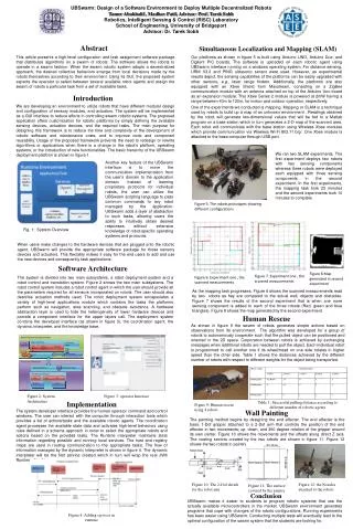
UBSwarm : Design of a Software Environment to Deploy Multiple Decentralized Robots Tamer Abukhalil , Madhav Patil , Advisor: Prof. Tarek Sobh Robotics, Intelligent Sensing & Control (RISC) Laboratory School of Engineering, University of Bridgeport Advisor: Dr. Tarek Sobh. Abstract.

E N D
UBSwarm: Design of a Software Environment to Deploy Multiple Decentralized Robots Tamer Abukhalil , MadhavPatil, Advisor: Prof. TarekSobh Robotics, Intelligent Sensing & Control (RISC) Laboratory School of Engineering, University of Bridgeport Advisor: Dr. TarekSobh Abstract Simultaneous Localization and Mapping (SLAM) This article presents a high-level configuration and task assignment software package that distributes algorithms on a swarm of robots. The software allows the robots to operate in a swarm fashion. When the swarm robotic system adopts a decentralized approach, the desired collective behaviors emerge from local decisions made by the robots themselves according to their environment. Using its GUI, the proposed system expects the operator to select between several available robot agents and assign the swarm of robots a particular task from a set of available tasks. Our platforms as shown in figure 5 is built using Arduino UNO, Arduino Due, and Digilent PIC boards. The software is uploaded on each robotic agent using UBSwarm interface running on a windows operating system. For distance sensing, URM V3.2 and PING ultrasonic sensor were used. However, as experimental results depict, the sensing capabilities of the platforms can be easily upgraded with other sensors, e.g., laser range finders. Additionally, the platforms are also equipped with an Xbee Shield from Maxstream, consisting on a ZigBee communication module with an antenna attached on top of the Arduino Uno board as an expansion module. This Xbee Series 2 module is powered at 2mW having a range between 40m to 120m, for indoor and outdoor operation, respectively. Introduction We are developing an environment to utilize robots that have different modular design and configuration of sensory modules, and actuators. The system will be implemented as a GUI interface to reduce efforts in controlling swarm robotic systems. The proposed application offers customization for robotic platforms by simply defining the available sensing devices, actuation devices, and the required tasks. The main purpose for designing this framework is to reduce the time and complexity of the development of robotic software and maintenance costs, and to improve code and component reusability. Usage of the proposed framework prevents the need to redesign or rewrite algorithms or applications when there is a change in the robot’s platform, operating systems, or the introduction of new functionalities. The basic hierarchy of the UBSwarm deployment platform is shown in figure 1. One of the experiments we conducted is mapping. Mapping or SLAM is a technique used by robots to build up a map of an unknown environment . Readings obtained by the robot will generate two-dimensional values that will be fed to a Matlab program on a base station which in turn generates a 2-D map of the scanned area. Each robot will communicate with the base station using Wireless Xbee modules which provide communication via Wireless Wi-Fi 802.11 b/g/. One Xbee module is attached to the base computer through USB port. We ran two SLAM experiments. The first experiment deploys two robots with two sensing components whereas three robots were deployed each equipped with three sensing components in the second experiment. In the first experiments, the mapping task took 23 minutes and the second experiments took 10 minutes to complete. Another key feature of the UBSwarm interface is to move the communication implementation from the user’s domain to the application domain. Instead of learning proprietary protocols for individual robots, the user can utilize the UBSwarm scripting language to pass common commands to any robot managed by the application. UBSwarm adds a layer of abstraction to such tasks, allowing users the ability to intuitively obtain desired responses without extensive knowledge of robot-specific operating systems and protocols. Figure 5: The robots prototypes showing different configurations Fig. 1: System Overview When users make changes to the hardware devices that are plugged onto the robotic agent, UBSwarm will provide the appropriate software package for these sensory devices and actuators. This flexibility makes it easy for the end users to add and use the new devices and consequently task applications. Software Architecture Figure 8 Map generated in second experiment Figure 7. Experiment one , the scanned measurements The system is divided into two main subsystems, a robot deployment system and a robot control and translation system. Figure 2 shows the two main subsystems. The robot control system includes a robot control agent in which the user should provide all the parameters required for all sensors incorporated on robots. The user should also describe actuation methods used. The robot deployment system encapsulates a variety of high-level applications module which contains the tasks the platforms perform such as navigation, area scanning, and obstacle avoidance. A hardware abstraction layer is used to hide the heterogeneity of lower hardware devices and provide a component interface for the upper layers call. The deployment system contains the developer interface (as shown in figure 3), the coordination agent, the dynamic interpreter, and the knowledge base. Figure 6. Experiment one , the scanned measurements As the mapping task progresses, Figure 6 shows the scanned measurements read by two robots as hey are compared to the actual wall, objects and obstacles. Figure 7 shows the results of the second experiment that is when one more sensing component is added to each of the three robots (Red, green and blue triangles). Figure 8 shows the map generated by the second experiment. Human Rescue As shown in figure 9 the swarm of robots generates simple actions based on observations from its environment. The algorithm was developed for a group of robots to autonomously cooperate such that the pulled object can be positioned and oriented in the 2D space. Corporation between robots is achieved by exchanging messages when additional robots are needed to pull the object. Each individual robot is programmed to call another one if its wheel/tread on one side rotates in higher speed than the other side. Table 1 shows the distances achieved by the different number of robots with respect to different weights for the object being transported. Robot Deployment Environment User interface Knowledgebase Coordination Agent Face Detection Obstacle Avoidance Navigation Device Agent HAL Robot Control Middleware Device Library Polling routine Hardware Components Xbee Sonar GPS Robot 1 Robot N Figure 2: System Architecture Figure 3: operator Interface Implementation Table 1: Successful pulling distance according to different number of robotic agents Figure 9: Human rescue using 4 robots The system developer interface provides the human operator command and control windows. The user can interact with the computer through interaction tools which provides a list of actions/tasks and the available robotic agents. The coordination agent processes the available state data and activates high-level behaviors using rules defined in a schema approach in order to select the appropriate robots and actions based on the provided tasks. The Runtime interpreter maintains state information regarding possible and running local services. The host and registry maps are used in routing communication to the appropriate tasks. The flow of information managed by the dynamic interpreter is shown in figure 4. The dynamic interpreter will be the first service created which in turn will wrap the real JVM Runtime objects. Wall Painting The painting method begins by designing the end effecter. The end effecter is the basic 1-Dof gripper attached to a 2-Dof arm that controls the position of the end effecter in two movements; up, down, and 360 degree rotation of the gripper around its own center. Figure 10 shows the movements and the offsets along direct Z axis. The coating sectors created by the two robots are shown in figure 11. Figure 12 shows the two robots in painting action. Figure 10: The 2-Dof sketch for the robot arm Figure 12: the Nozzles attached to the robots Figure 11: The surface covered by the painter Conclusion UBSwarm makes it easier to students to program robotic systems that use the actually available microcontrollers in the market. UBSwarm environment generates programs that cope with changes of the robots configurations. Running experiments has been easier using UBSwarm. Conducting multiple tests will eventually lead to the optimal configuration of the swarm system that the students are looking for. Figure 4: Adding services in runtime