Download
1 / 13
140 likes | 417 Views
EPICS on TPS RF System. Yu-Hang Lin Radio Frequency Group NSRRC. Outline. History & Current Status TPS RF System TPS RF Transmitter Control Structure TPS RF Test Area & Archive Telephone Alarm System Summary. History & Current Status. Why EPICS?

E N D
EPICS on TPS RF System Yu-Hang LinRadio Frequency GroupNSRRC
Outline • History & Current Status • TPS RF System • TPS RF Transmitter Control Structure • TPS RF Test Area & Archive • Telephone Alarm System • Summary
History & Current Status • Why EPICS? • In 2007, director of RF group says “Instrument and control group decided to use EPICS. We also have to study EPICS.” • Team member for studying EPICS in RF group – one – me. • Currently we use EPICS for – • Data archive • Remotely system monitor • Telephone alarm system
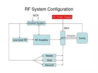
TPS RF System • 300 kW transmitter by Thomson (turnkey system) (2 sets) + THALES Klystron (2 for operation, 2 for spare) • Home-made low level RF system (4 sets) • PETRA cavities (normal temperature) for booster routine operation • KEKB cavities (super-conducting) for storage ring routine operation • Home-made electronicscontrol systems for super-conducting RF (3 sets)
TPS Transmitter • Transmitter • Power supply • Cooling system • Amplifiers • RF loads • Control system • Interlocks in control system • fast interlock by ICS (interlock control system) • slow interlock by Siemens PLC • All signals and status are monitored by EPICS IOC.
TPS Transmitter Control System • A Siemens S7-300 PLC control the startup and shutdown procedure of transmitter. • EPICS IOC (on CPCI single board computer with Linux operating system) communicates with PLC via TCP on Ethernet (PSI S7PLC driver). • EPICS IOC has no authority to write data to PLC but reading. • Two human-machine interface (HMI) touch panels are in charge of displaying and setting functions of PLC. • PLC communicates/controls ICS and PSMC via serial communication over Siemens protocol and ASCII protocol.
TPS Transmitter Control System • A Siemens S7-300 programmable logic controller (PLC) controls all the startup and shutdown procedures. • Two (local/remote) human-machine interfaces (HMI) are in charge of displaying and setting functions of PLC. • Only one – either the local HMI or the remote HMI – can perform the system operational functions at one time. • A hardware switch on the front panel switches the privilege of control between local and remote HMI. • EPICS interface layer communicates with PLC via TCP/IP for data collection only, i.e. EPICS has no authority to control the RF transmitter system.
SRF Module in RF Lab • Storage area: before and after module assembly. • Coupler installation • Small portable clean booth • End group assembly • Component cleaning, assembly, one-month-baking, storage. • Horizontal tests • Cryogenic cooling power, test Dewar, bayonet joint. • RF source, radiation shielding, measurement instruments. • Pumps/gauges for cavity vacuum and insulation vacuum. • Data recording => EPICS Channel Archiver
Horizontal Test at SRF Lab SRF Module in RF Lab
Archive System in RF Lab • Too many signals need to be monitored/recorded during the horizontal test • Temperatures of cavity and cryogenic pipes • Flow rates of cooling water and cryogenic system (Nitrogen and Helium) • Opening scale of valves • Pressures of SRF module • Vacuum … • DTACQ ACQ196 provides a good solution to high density environment. (96 channels within a single board) Cornell super-conducting cavity (S0) cool down / warm up procedure in last 3 months. Cavity top temperature / bottom temperature
Archive System in RF Lab Cornell super-conducting cavity (S0) cool down / warm up procedure in last 3 months. Cavity top temperature / bottom temperature
Telephone Alarm System • Data collection server collects all monitored data from EPICS and other data archive servers via UDP or TCP protocols. • Alarm rules are stored in the data collection server. • Control PC periodically asks data collection server the alarm statuses. • Control PC equips a dialing device (AD120) which connect to telephone line. • Once a signal satisfies its alarm conditions, control PC will automatically contact persons with speeches to distinguish which sub-system fail.
Summary • Currently, EPICS is not used to control any device on RF system. Only data collection and distribution are allowed. • Ethernet-wide broadcasting makes EPICS being a good tool in data recording. • EPICS is a main data recording tool on RF system in test area, especially during the TPS RF transmitter acceptance test and KEKB superconducting horizontal tests. • EPICS IOC on embedded Linux for digital LLRF will be developed after TPS RF project.