Download
1 / 41
420 likes | 545 Views
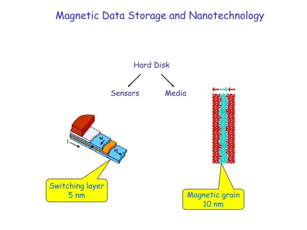
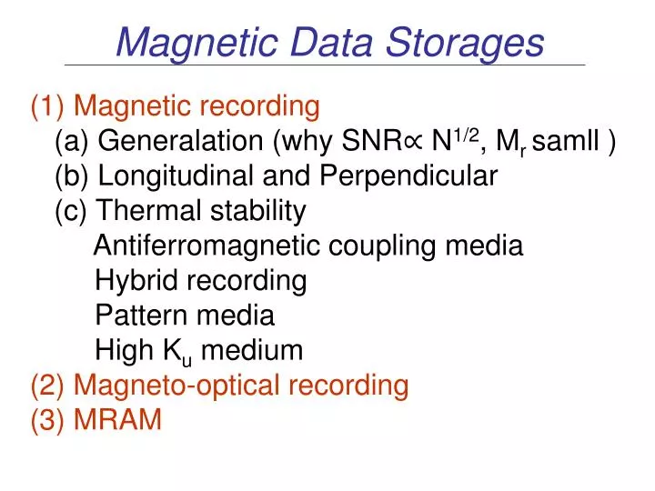
Magnetic Data Storages. Magnetic recording (a) Generalation (why SNR∝ N 1/2 , M r samll ) (b) Longitudinal and Perpendicular (c) Thermal stability Antiferromagnetic coupling media Hybrid recording Pattern media High K u medium

E N D
Magnetic Data Storages • Magnetic recording (a) Generalation (why SNR∝ N1/2, Mr samll ) (b) Longitudinal and Perpendicular (c) Thermal stability Antiferromagnetic coupling media Hybrid recording Pattern media High Ku medium (2) Magneto-optical recording (3) MRAM
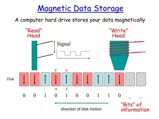
Schematic representation of longitudinal, digital magnetic recording write process.
The recording medium When there are fewer particles per bit, the transition between domains becomes less sharp and pickup signal decreases. Why not make each recorder region a single domain particle or grain ?
Transition width Hx(x,0)≈4Mrδ/x Horizontal fringe field hx for a longitudinal transition of zero width (a=0) and for a = 0.5 at y = 0, 0.5( Eq.1), respectively. (1)
y Schematic representation of field above a longitudinal recording medium.
The coecivity squareness parameter S* is defined as S* = 1 – Mr / xoHc , xo = [∂M/∂H]Hc S* varies from 0 to 1 The switching field is defined as SFD=ΔH/Hc ,ΔH is the full width at half maximum as indicated in the fig. High SFD implies a spatially sharp and requires a narrow magnetisation transition particle size distribution.
Material Requirements For recording media • When there are few particles per bit, the transition • between domains becomes less sharp and pickup signal • decreases. About 1000 isolated particles. (2) The more irregular transition are referred to as zigzag or sawtooth transitions. Noise is due primarily to the formation of zigzag transition between bits. the sawtooth pattern scales roughly as Ms2/K1/2, the solutions: decreasing Mrt and increasing K. (3) The signal is proportional to the number of measured events or particles per bit, N. Hence SNR ~ N1/2. (4) The heads must approach to the hard disc surface.
Write head : having a sufficient high Ms so that the fringe field exceeds the Hc of the medium (500-3000Oe); an adequate magneticpermeability (easy saturated). Read head:low Hc, low noise and extremely high permeability in order to respond with a substantial change in flux to the weak fringe field above the medium
Schematic M-H loop for ideal magnetic recording medium and head material. For write head: µ >>1, Ms large and Br=0; For read head: µ >>1 , Hc = 0
Thin film recording head Film thickness 2-3 micrometer; Gap 200 nm. Thin film recording head. Left, layout of pole pieces and windings; right, enlarged, cross-sectional view of magnetic pole pieces
High frequency 109Hz; A weak uniaxial anisotropy; High electrical resistivity Permeability versus frequency for four thin films.
Magnetoresistive head Field dependence of magneto- resistivity for uniform response to a uniform field. Geometry of magnetoresistive sensor showing sense current, anisotropy field, and external or fringe field of medium, and their effect on magnetization. h=1-2 µm, w=2-4 µm t=10-20 nm Δρ/ρ =2.0% Ni81Fe19
Spin-Valve Read head Structure of a simple spin valve; the device dimention are approximately h=2-6 µ m and w=10 µ m .
M2 M1 Experimental transfer curve for a 2 µ m high spin valve sensor for +5mA (solid) and -5mA (dashed) sense current.
Longitudinal and perpendicular recording Comparision of recorded bits in longitudinal (a) and perpendicular (b) media. Demagnetization factor for a recorded bit : (a) proportional to Mrt/ λ; and (b) to Mr λ/ t. Linear bit density: (a) 105 bit per inch (λ=0.5 µ ); and (b) 105 -5x10⁵ bpi
Perpendicular recording using flux closure layer beneath the medium (Iwasaki et al., IEEE Trans. MAG-15, 1456(1979)).
Thermal Stability • In the physics of magnetic recording there are two key • factors in achieving very high areal density: • The superparamagnetic effect (thermal stability); • The finite sensitity of the readback head. • In both cases, the limitations arise because the signal • energy becomes so amall as to be comparable with • the ambient thermal energy.
The signal to media noise is approximately by the number of magnetic grains (or switching units) per bit: SNRmedia~ Wbt / vg Where, wbt (bit volume, read-width x bit-length x thickness) vg (the grain volum) In order to avoid thermal instability, a minimal stability ratio of stored magnetic energy, KuV, to the thermal energy, KBT, KuV/KBT ≌ 50 - 70
Interlayer antiferromagnetic coupling media Longitudinal Schematic illustration of (a) a two layered AFC media, (b) LAC media with high J and (c) advanced three layers LAC media for much lower Mr δ .
In the case of two layers AFC media Mrt = Mr t1 – Mr t2 KuV1<KuVeff < (Ku V1+KuV2) KuV/KBT ≌ 50 - 70 Magnetic hysteresis loop for a single layer media (a) and an AFC media (b). Jex=0.06 erg/cm2, Hex~800 Oe.
Fitted by Eq.(1) (1) Where tp is about 1 s and fo~109 Hz; from the fit, we obtain Ho=8.6 KOe, KuV/KBT=75 for the single layer; Ho=8.3 KOe, KuV/KBT=100 for AFC one. • Room temperature HcR vs Mrt for • single layer media and AFC media • (b) Thermal decay.
Interlayer antiferromagnetic coupling media Perpendicular Magnetic loop as a function of Ru thickness Interlayer antiferromagnetic Coupled two grains
Correlation between exchange field, Hex, coecivity field, Hc, and nucleation field, Hn.
Normalized effective energy barries, KVeff/KV1, as a function of the apparent exchange coupling Japp.
hybrid recording (Solid immersion lens) ZnS:SiO2 NA ~1.1 Media: Co69.48-xTb30.52Agx, x=0-25.68
Patterned Media Low noise, high density Scanning electron microscopy image of a square array of electodeposited Ni pillars of high 300nm and period.
High Ku Materials Approach to 100 Gbits/in2 • Smaller, thermally stable media grains • Prominent candidates are RE-TM Co5Sm and L1o phases FePt (Hc >1T), CoPtY….. • 3 times smaller grain diameters d and potential 10 fold areal density increase (∝1/d2) •Write field 10-100KOe KuV/kT>40-60 D.Weller et al., IEEE Trans on Mag., 36(2000)10
Magneto-optical Recording Principle of thermomagnetic recording (Curie point writing): (a) before, (b) during and (c) after the writing.
Temperature dependence of the magnetization for a GdCoMo amorphous alloy films (Chaudhari et al., APL 42(1973)202).
The condition of a written stable bubble domain* Huth’s equation (1974 IBM J..Res.Dev. 10 100-9) Where r is the domain radius, Hd the demagnetizing Field, Hext the applied external field and σW the wall energy density of the magnetic medium. The spot size and signal to noise d=λ/(2NA); S/N ~ θKR1/2 * Bobeck IEEE Tran. Mag., MAG-5(1969)554.
From Oppeneer Magneto-optical Kerr spectra in Handerbook of magnetic Materials, Edited by Buschow (Vol.13) Experimental pola Kerr ritation an undoped MnBi sample (Di et al. 1992) and Al-doped MnBi (Shang et al., 1997) sample at room temperature.
High-density MRAM (Magnetic random access memories) Schematically representation of MRAM structure and M-H, ΔR/R characteristics of the PSV.
Schematic of the read and write processes in a PSV random access memory.
Table: composition and dimensions of the principle layers in a current representative MARM device.
Outlook and Fundamental Limits to Recording • The bit density limit of thin film media is estimated to be approximately of order 100 Gb/in2. • If bit size, λ/2, is to decreases,the write gap, g must decreases and the write head must be closer to the medium. • smaller λ demands that the medium is reduced. The fringe field decreases and signal strength drops even more.The read head, then, must be either more sensitive or closer to the medium. • Thus, all of the relevant dimension of the recording process need to be scaled down together to achieve high recording density. • Thermal stability