Download
1 / 20
200 likes | 427 Views
Reflector Antenna Jason Miksovsky Abhishek Khanna Mohammed Arif Peter Krammer. Two main purposes of Antenna. Impedance matching: matches impedance of transmission line to the intrinsic impedance of free space to prevent wanted reflection back to source.

E N D
Reflector Antenna Jason MiksovskyAbhishek KhannaMohammed Arif Peter Krammer
Two main purposes of Antenna • Impedance matching: matches impedance of transmission line to the intrinsic impedance of free space to prevent wanted reflection back to source. • Antenna must be designed to direct the radiation in the desired direction.
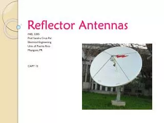
Reflector Antenna • Reflector antenna such as parabolic antenna are composed of primary radiator and a reflective mirror. Source: http://ksrs.or.kr
Parabolic Reflector Antenna • Any electromagnetic wave incident upon the paraboloid surface will be directed to the focal point. • Primary antenna is used at the focal point of the parabolic reflector antenna instead of isotropic antenna. The isotropic antenna would radiate and receive radiation from all directions resulting in spillover. • Primary antenna should be designed to “illuminate” just the reflector uniformly.
Characteristics • Effective area of reflector antenna: • Projected physical aperture: • Gain: • Loss in efficiency due to due to radiation in undesired direction • Spillover loss • Focal point errors • Feedhorn sidelobes • Imperfections in parabolic surface • Feedline line
Characteristics • Aperture: r= radius of the diameter • Larger dish has more gain than smaller • Clear line of sight is important Source: Lecture (12/05/02)
Calculations • Physical area: • D= Diameter • Effective area: • = illumination efficiency • Wavelength: • Gain: • 3db beamwidth:
Half power beamwidth The half power graph showing the angle between the half power point on either side of maximum
DIRECTV Specs • D of reflector = 18” = 0.457 m • Operating frequency = 12.4 GHz • Illumination Efficiency (http://www.mitre.org/pubs/showcase/fcc_may01/mitrereport_4_01.pdf)