Download
1 / 44
440 likes | 450 Views
This workshop presentation discusses the feasibility of transfer-induced fission experiments at TSR@ISOLDE, including the physics motivation, detector setup, and target lifetime modification due to gas target.

E N D
Feasibility of experiments at TSR@ISOLDE from the accelerator point of view Manfred Grieser Max-Planck-Institut für Kernphysik TSR at MPI für Kernphysik TSR@ISOLDE workshop, CERN, 27th -28th April 2015
Fission Experiment at TSR@ISOLDE Transfer induced fission experiments proposed by Beatriz Jurado physics motivation and explanation of detector setup will be given by B. Jurado tomorrow gas jet stored ion beam target like telescope fission fragment detector stored ion beam gas-target proof of principle experiment:
Lifetime modification due to gas target target thickness nt : intensity multiplication factor life time due to target density n- target density f0-revolution frequency life-timedue to electron capture in the cooler and residual gas interactions main loss process in the target: electron capture remark for H2 targetM=2 He target M=1 Schlachter formulae: cross section in 1/cm2 E projectile energy in keV, A mass number, Zgas-targetatomic number, qion charge At TSR energies:
Target Life time and optimum charge state beam life time determined by electron capture in the target E in keV At TSR energies: p- ion momentum Q=qe0 ion charge maximum beam rigidity: =1.5 Tm E as a function of q s as a function of q for Br =1.5 Tm and 232Th for Br =1.5 Tm and 232Th Emax = A10 MeV/u 3He target q=71 life time as a function of q at Br=1.5 Tm for 232Th result E= 2320 MeV for Br=1.5 Tm: q=71 fortarget thickness nt=1013 1/cm2 ttarget= 0.75 s for 3He target with nt=10131/cm2 ttarget(s) (He target) remark:
Charge State in REXEBIS Estimated attainable charge states in REXEBIS as a function of ion Z (ref. TSR@ISOLDE TDR) bare ions Z=90 (Thorium) Stripping of Th ions at 2320 MeV (10 MeV/u) : carbon foil: equilibrium charge state: 72close toq=71(calculated with LISE 9.10.62)
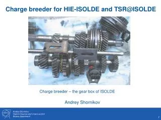
Upgrade of REXEBIS A new EBIS, producing much higher charge states is under investigation at CERN Design parameters HIE-ISOLDE / TSR@ISOLDE breeder new TSR@Isolde charge breeder With the new TSR@Isolde charge breeder bare ions up to Z=60 should be possible Much more details about this project was given by Fredrik Wenanderduring the last TSR@ISOLDE 2014 workshop at CERN
Lifetime of 232Th71+ with E=2320 MeV in the TSR Br=1.5 Tm target: for target (He) thickness nt=1013 1/cm2 : ttarget= 0.75 s for target (He) thickness nt=1012 1/cm2: ttarget= 7.5 s for p=510-11 mbar: vacuum life times electron capture: tcap=100 s multiple scattering: tms> 106 s stripping: neglect able maximum possible electron current: Ie=0.43 A, aex=9.3: tREC= 4 s reduced electron current: Ie=0.1A, aex=9.3: tREC= 16 s ECOOL ti- life time of loss processes total life time t: for very high target densities (nt>51012 1/cm2):
232Th71+ injection: electron stacking ECOOL stacking scheme: injection rate nr: determined by electron cooling time tECOOL: where: A-ion mass q-ion charge Ie- electron current Ie max –maximum possible electron current for 0.03<ß<0.16 but
Space charge limit due to inchoherent tune maximum possible stored ion number: -DQ - possible incoherent tune shift TSR: -DQ0.065-0.1 for B=1 with and (aex=const) constis calculated from the 12C6+data: intensity limit: stability limit incoherent tune shift I 1 mA space charge limit: 232Th 71+ (E=10232 MeV) : I= 1.9 mA N= 2 108
Luminosity definition of luminosity: R(t)-reaction rate s- cross-section N(t)-number of stored particles f0-revolutionfrequency nt-target thickness n-target density remark: -due to possible switching of the target, owing to better lifetimes and lower 3He (very expensive) consumption, target thickness nt depends on time - a strong variation of the particle number N(t) may occur due to separated injection (intensity increase) and experiment (intensity decrease) cycle
Ion Number and Luminosity periodical change of N(t) periodical change of luminosity space charge limit T ECOOL stacking experiment target on target off average luminosity: life time: t1=14 s life time: t2=0.7 s measuring time per period: 2t2 7 multi turn injections with Ni=3 107ions and nr =1.8 1/s nt=1013 1/cm2 for232Th71+ beam E=2320MeV (f0=0.786 MHz)
Ion Number and Luminosity periodical change of N(t) periodical change of luminosity space charge limit equilibrium between injection and beam looses N0=nrNi ECOOL stacking experiment target on nt=1013 1/cm2 average luminosity: life time: t1=0.7 s life time: t2=0.7 s measuring time per period: 2t2 with Ni=3 107ions and drastically increased electron current: Ie=0.28-0.43 A injection rate: nr =5 1/s for232Th71+ beam E=2320MeV (f0=0.786 MHz) maximum possible nr
Luminosity at continues injection and measurement particle number N(t): Ni-injected particle number per injection nr- injection rate t- total lifetime for high target densities the beam lifetime is very short and determinedby the target lifetimett. In the equilibrium: stored number of ions N0 (N0Ns ): N0 - equilibrium particle number Ns -space charge limit (E=2320 MeV 232Th71+ andHe target) nt-targetthickness11 with: and const=0.75·1013 s/cm2 It follows for the luminosity L: and independent of the target thickness ! (nt>51012 1/cm2) example: f0=0.786 MHz Ni= 3 ·107 nr,max=5 1/s He target L 9·1026 1/(s·cm2) stacking to the space charge limit requires Ni =6 ·107 and results in maximum possible luminosity L 1.8·1027 1/(s·cm2) (He-target)
Halo formation during ECOOL stacking beam at the target location very dense stack with cooled ion beam halo: hot injected ion beam, which is cooled down until next injection proceed cooling process ratio of number of ions in halo Nhaloand stack Nstack target thickness repetition rate of multi turn injection
Minimization of the halo size during measurement -measurement starts after a certain delay Tdelay after injection and ends before the next multi-turn injection takes place timing scheme measurements T optimum TdelaytECOOL Te Tdelay t multi turn injections examplefor232Th71+ (E=2320 MeV) measurements advantage: -halo: size significant reduction number of particle significant reduction -almost constant beam current and counting rate -no switching of gas jet disadvantage: -luminosity reduction by factor: Te/T T=0.2 s electron current: Iemax=0.43 A electron beam power: 0.43 A0.5860 kV=2.5 kW
Background by Coulomb scattering in the target fission fragment detector stored ion beam opening for stored ion beam gas jet (target) energy scatter angle relation of Rutherford scattered Th ions - directly after scattering ion will pass the fission fragment detector, but acceptance angle of the TSR due to the small detection angle of scatted fission fragments, the fission fragment detector may determine the ring acceptance • collision of scattered ions after a few turns with fission detector 232Th71+ E=2320 MeV
Background by Coulomb scattering in the target energy scatter angle relation of Rutherford scattered Th ions -further there is a momentum shift of the scattered Th ions of up to -2.6% closed orbit shift by D- dispersion in the target area leading to an increaseof the betatron oscillation around the new closed orbit • possible collision with the fission target after a few turns 232Th71+ E=2320 MeV target protection with an aperture or scraper fission detector gas jet moveable aperture or scrapers ion beam remark: aperture protect also detectors against Injected ion beam diameter d2 diameter d1 with d1>d2 (symmetry position)
Low Beta Mode ? center straight section Low Beta TSR Mode target shift fission detector gas jet s target ion beam detector shift aperture shift small aperture old beam profile monitor position quadrupole family 7 quadrupole family 6 quadrupole family 7 target quadrupole family 6 In the low beta mode the number of quadrupole family is increased from 5 to 7,creating a small beta functions in the center of a straight section and increasing rapidly with s: ß0 beta function in the center • To benefit from the low beta mode fission detector has to be in the center of the straight section • shift of the detectors towards center of straight section required shift of the gas target downstream to the beam direction
Cold ion beams for external spectrometer HELIOS information about HELIOS spectrometer was given in the talk by Sean J Freemann at last TSR@ISOLDEworkshop 2014 and will be given by Robert Page, tomorrow HELIOS spectrometer possible location of HELIOS spectrometer HELIOS TSR beam from HIE-ISOLDE picture from talk of Sean J Freemann, TSR@ISOLDE 2014 workshop beam requirement: transverse emittance ≤ 0.01 mmmrad FWHM energy spread 0.025% Peter Butler, technical note, June 12 2014
Emittance and momentum spread of an electron cooled ion beam 10-4 equilibrium emittances and momentum spread of cooled ion beams as a function of particle number for the ion species: D+, 6Li3+ ,12C6+and 16O8+ (ne= 8106 cm-3,Bcool=418 Gauss, b=0.11) N 108 107 109 definition of emittances: horizontal and vertical emittance is defined by the s values of the horizontal and vertical beam size: 0.01 N 107 108 109 0.01 momentum spread: momentum spread is rms value: 0.001 N 108 107 109
Slow Extraction at the TSR horizontal phase space electrostatic septum for injection and extraction • working point shifted close to a third order resonance Qx=2.6666… • third order resonance is exited by one or two sextupoles • creating a separatrix around the stored ion beam • inside the separatrix ions can be stored stable • if ions reaches the separatix ions are moving along the separatrix towards the electrostatic septum foil, jumping into the field of the septum and are extracted • excitation of betatron motion inside the separatrix is done by rf noise given to a kicker where the ECOOL has to be off • with the noise level the extraction rate can be affected
Extraction experiment with 12C6+ E=73.3 MeV ions Development of the horizontal beam profile 1.3 s noise on horizontal beam width (mm) t=4 s maximum profile and counting rate counts time (s) extraction rate (kHz) noise off x (mm) time (s) ECOOL on for 1s 1.8 s the first ions are reaching the separatrix
Measured emittance of the slow extracted beam beam:12C6+ E=73.3 MeV cooled stored beam without extraction N=4107 ex,s= 0.02 mm·mrad ey,s= 0.04 mm·mrad Measured emittances of the slow extracted beam : number of injected ions: N= 2.7 105 (I=0.15 mA) horizontally: ex,2s= 1±0.2 mm·mradex,s=0.25±0.05 mm·mrad vertically: ey,2s=1.1±0.1 mm·mrad ey,s= 0.275±0.025mm·mrad stored ion beam: ey,s= 0.245±0.019 mm·mrad measured for 12C6+ E=73.3 MeV and ne=8106 cm-3 emittance definition: momentum spread of slow extracted beam: was not measured
Horizontal emittance of extracted beam horizontal emittance of slow extracted beam is determined by the extraction method and momentum spread Dp/p beam with momentum spread mono energetic beam extracted ions (for simplification the dispersion at the septum: D=0 m, D`=0). ions are extracted along a straight line in the transverse phase space =0 ! divergence Dx’ of extracted beam horizontal beam size Dx is given by the three turn separation at septum position with Dx’>0 e>0 Hardt condition D’<0 for D>0 m (D-dispersion at septum) to suppress Dx` cannot full filed
Momentum spread momentum spread of stored ion beam is affected by the rf noise field given to the kicker, used to increase the betatron amplitude during extraction E||f(t) E||i(t) ion beam If the flight time to the kicker integer number of rf period 1/frf fringing field almost no effect to momentum spread !! T- flight time through the kicker ,frf -center frequency of rf noise, f0-revolution frequency, n,m- integer number, q- non integer part of the tune q0.66,C0- circumference, L- kicker length • new extraction kicker working at relatively high frequencies C0/L·f0 condition
Intra Beam Scattering (IBS) effects -reduction of the longitudinal heating effects may reduce the momentum spread and improves the horizontal emittance of the extracted beam. • But there is an increase of the horizontal, vertical and the momentum spread in the TSR due to IBS: for the slow extraction process electron cooling has to switch off blow up of the horizontal, vertical and momentum spread by IBS in the ring • horizontal emittance of extracted beam not influenced by IBS, because it is determined by the slow extraction process - but vertical emittance and the momentum spread of extracted beam are affected by IBS horizontal beam width vertical beam width ECOOL off ECOOL off ß=0.11 ß=0.11
Modifying the slow extraction scheme • electron cooling has to be permanent on to cool the vertical and longitudinal degree of freedom during the extraction process • increase the horizontal rf noise level to overcome electron cooling force -this process can be supported by dispersive electron cooling where the horizontal cooling force are transferred in the longitudinal degree of freedom, or opposite . Dispersive electron cooling is realized by using an horizontal gradient in the horizontal cooling force realized by shifting the electron beam and applying dispersion in the electron cooler horizontal and vertical cooling rate measured with 73 MeV 12C6+ D 2 m D2 m 1/tx,disp (1/s) ne=8·106 cm-3 • switching off horizontal cooling and horizontal heating with the electron beam should be possible !! noise reduction transferred to the horizontal kicker x(mm) horizontal position of the ion beam to the center of electron beam
Dispersive electron cooling, longitudinal cooling force Longitudinal friction coefficient F||(v||)- longitudinal cooling force Transverse cooling force is transferred to longitudinal cooling by dispersive electron cooling D2 m a||+ax+ay=constant x(mm) transfer of cooling force vertical cooling force remains constant Active vertical and improved longitudinal (a||→0 or a||<0 ) electron cooling during the slow extraction process ! Enhanced active longitudinal electron cooling will reduce the horizontal emittance of the slow extracted beam significantly !
Horizontal emittance of slow extracted beams horizontal emittance of slow extracted beam is determined by the extraction method and momentum spread Dp/p • compression ofDx’ with • active and improved • longitudinal electron cooling • significant reduction of the horizontal beam emittance ! extracted ions horizontal beam size Dx is given by the three turn separation at septum position (for simplification the dispersion at the septum: D=0 m, D`=0, this condition is approximately fulfilled at the TSR if dispersive electron cooling is applied). • This slow extraction scheme combined with dispersive electron cooling is not • tested so far !!! Alternatively fast extraction can be used to extract an cold ion beam
Fast extraction at the TSR For fast extraction the phase advance between kicker and electrostatic septum: -extraction kicker huge device - dimensions only very roughly known -worst case: removing quadrupole family 3 to provide enough space for the kicker location of fast extraction kicker fast extraction kicker quadrupole family 3 septum HIE-ISOLDE beam extracted beam injected beam extracted beam standard mode
TSR lattice with four quadrupole families ß function Standard Mode SP=4 Qx=2.84 Qy=2.91 removed quadrupole family dispersion function
Fast Extraction septum deflection anglea=40 mrad dipoles to experiment extracted beam electrostatic septum beam direction dipole dipole LB12 LB11 time independent closed orbit shift dipoles for closed orbit shift extraction orbit extractionkicker closed orbit HIE ISOLDE beam beam direction extracted beam For fast extraction the closed orbit is shiftedpermanently towards the electrostatic septum by about 60 mm a fast kicker deflect the ion beam by around 17 mrad. Leading to a beam deflection of 30 mm at the location of electrostatic septum, therefore the total beam deflection in front of the septum is 30+60mm=90 mm In the electrostatic septum the extracted ion beam is deflected by about 40 mradand transferred to the experiments
Fast extraction kicker specifications fast kicker specification for a rough cost estimation from CERN maximum beam rigidity: 1.5 Tm deflection angle: about 20 mrad response time (from B=0T to 0.9 Bmax): about 200 ns (roughly), preferable 100 ns maximum length of the kicker: below 1 m (if possible) (to avoid removing of quadrupole family 3) kicker chamber (inside): horizontal width of at least 100 mm, 200 mm (preferable) vertical height: ≥ 55 mm remark: kicker has switching time, defined by the respond time coasting beam: causes movement of the extracted beam to avoid movement bunching + ECOOL increasing of emittance and momentum spread kicker specification requirements fulfills: • two modules of the LEIR/CERN extraction kicker • fast injection kicker for ELENA/CERN (roughly) remark: fast ELENA injection kicker can be used also as an extraction kicker fulfilling our demand for an 20 mrad deflection angle at Br=1.5 Tm, but the field quality of the horizontal field is less than expected
Rough cost estimation for the extraction kicker very rough cost estimation from Brennan Goddard and TE-ABT group/CERN from 14. April 2015 can increased to 100x55 mm based on ELENA kicker • removing of quadrupole family 3 maybe not necessary !!! total length=1000 mm total cost: 1005 kCHF CERN manpower: 4.4 FTE Maintenance of magnets, generators etc. : 50 kCHF per year
Acknowledgement Peter Butler, University of Liverpool, Liverpool Brennan Goddard, CERN, Geneva Beatriz Jurado, CENBG, Gradignan Shabab Sanjari, GSI, Darmstadt Luc Sermeus, CERN, Geneva Fredrik Wenander, CERN, Geneva
Single scateing in gas targets -CMS System Rutherford scattering: energy laboratory system acceptance angle laboratory system cross section for particle loss acceptance angle CMS system life-time 232Th71+ E=2320 MeV and3He target with nt=1013 1/cm2: Tsc 14000 s (negligible)
ECOOL stacking with 12C6+ ions (E=73.3 MeV) at the TSR Intensity increase during ECCOL stacking I(t)-stored intensity Im-intensitystored with a multi turn injection nrinjection rate tbeam life time working diagram I=1.2 mA t1000 sat low intensity Intensity drop start to decrease beam life time Qx=2.75 fourth order resonance Q=2.75 should beavoided! possible incoherent tune shift without reducing beam life time: fourth order resonances third order resonance
Ion Number and Luminosity periodical change of N(t) periodical change of luminosity space charge limit equilibrium between injection and beam looses N0=nrNi ECOOL stacking experiment target on average luminosity: life time: t1=0.7 s life time: t2=0.7 s measuring time per period: 2t2 4 multi turn injections with Ni=3 107ions and nr =1.8 1/s nt=1013 1/cm2 for232Th71+ beam E=2320MeV (f0=0.786 MHz)
Time development of the vertical beam profile vertical beam profile during the slow extraction process vertical beam width (mm) horizontal rf noise to the kicker ECOOL off rf noise off time (s)
Comparison of bunched and coasting beams horizontal beam profile ECOOL off bunched beam sx (mm) coasting beam t (s)
Elena Injection kicker →TSR fast extraction kicker ? slide from Wolfgang Bartmann (CERN), ELENA review CERN,15-16 October 2013 Existing (1986), from AA ring Magnet installed into new vacuum tank to be bakeableupt 300 deg in situ HV power converter recuperated from AAC PFL (SF6, 15 Ohm, 40kV) discharged by fast thyratron switches Terminated by matched resistor Pulse length can be adjusted with a dump thyratron Polarity reversal by swapping HV in/out cables in magnet connection box 15-16 Oct 2013 ELENA review, Inj/extr and transfer lines 42
ELENA Injection kicker parameters slide from Wolfgang Bartmann (CERN), ELENA review CERN,15-16 October 2013 too small too small 15-16 Oct 2013 ELENA review, Inj/extr and transfer lines 43
LEIR extraction kicker from PIL/LEIR design report, C.Carli, M. Chanel, S. Maury two modules are required one module